Courtesy of Steven Engineering, Inc. Ÿ 230 Ryan Way, South San Francisco, CA, 94080-6370 Ÿ Main Office: (650) 588-9200 Ÿ Outside Local Area: (800) 258-9200 Ÿ www.stevenengineering.com
MSC OPEN SIGNAL Family
Model MSC-C/C Single Channel Module
NOTE: THIS IS A FACTORY CONFIGURED UNIT
FACTORY CONFIGURATION
Part #: 10-1000-XX:
4 to 20mA Input; 4 to 20mA Output
SensorPulse model MSC-C/C has been configured
as indicated above.
The unit may be re-configurated to accept a 0 to
20mA, 0 to 10mA, 4 to 20mA, ±10mA, or ±20mA
input signal and provide a 0 to 20mA or 4 to
20mA output signal. Unit re-configuration requires SensorPulse’s SignalFlex™ Configuration
Utility.
This MSC unit may be reconfigured by a user at
any time via their personal computer (PC) or
handheld personal computer (HPC) by installing
SensorPulse Corp.’s Windows®/PC or Windows®/
CE HPC based SignalFlex™ Configurator Utility,
interfacing the MSC unit to the computer’s RS232C comm port with an MSF Configuration
Cable, and then changing the unit’s input/output
configuration settings.
OPERATIONAL DESCRIPTION
The MSC family of single channel signal conditioning and isolating modules are intelligent, user
programmable, high-accuracy, user friendly, signal conditioning units.
Each MSC model supports a one (1) specific analog signal-type on its input channel and outputs
one (1) high-level current or voltage signal depending upon model. A diverse MSC model family permits users to select the model which meets
their unique signal conditioning needs.
WIRING
TERMINALS
MSC models may be purchased with a factory preset configuration for plug-n-play application or
custom configured to meet their unique need. All
MSC models may be configured/reconfigured by a
user at anytime through use of an optional
SignalFlex™ Configuration Utility.
Theory of Operation - An analog world input
signal arriving at the MSC unit is isolated, filtered,
amplified, scaled and/or linearized (as required) by
the units onboard microprocessor under the direction of the unit’s configuration parameters set by
the user (or factory) via Windows®/PC or Windows®/CE HPC (Handheld Personal Computer)
based SignalFlex™ Configurator Utility.
The conditioned signal is then converted to a high
level analog current or voltage output signal (depending upon model) and presented at the unit’s
isolated output.
REQUIREMENTS
Mandatory:
• 15 - 32VDC, 30mA external supply voltage
Optional:
• SignalFlex™ Configuration Package (Part
No. MSF-CC-A1) Package consists of:
SignalFlex™ Configurator Utility and MSF
Configuration Cable.
3. Connect input current device to MSC unit:
Positive (+) to MSC terminal +V/C IN
Negative (-) to MSC terminal -V/C IN
4. Connect output actuator/device to MSC unit:
Positive (+) to MSC terminal +OUT
Negative (-) to MSC terminal -OUT
DIAGNOSTIC TOOLS
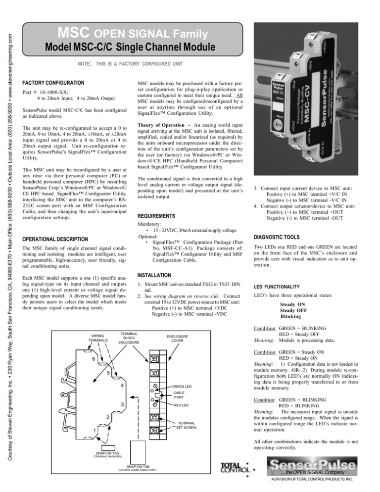
Two LEDs one RED and one GREEN are located
on the front face of the MSC’s enclosure and
provide user with visual indication as to unit operation.
INSTALLATION
1. Mount MSC unit on standard TS32 or TS35 DIN
rail.
2. See wiring diagram on reverse side. Connect
external 15 to 32VDC power source to MSC unit:
Positive (+) to MSC terminal +VDC
Negative (-) to MSC terminal -VDC
TERMINAL
BLOCK
ENCLOSURE
ENCLOSURE
COVER
6
5
4
GREEN LED
CABLE
PORT
3
RED LED
2
TERMINAL
SET SCREW
1
LED FUNCTIONALITY
LED’s have three operational states:
Steady ON
Steady OFF
Blinking
Condition: GREEN = BLINKING
RED = Steady OFF
Meaning: Module is processing data.
Condition: GREEN = Steady ON
RED = Steady ON
Meaning:
1) Configuration data is not loaded in
module memory. -OR- 2) During module re-configuration both LED’s are normally ON indicating data is being properly transferred to or from
module memory.
Condition: GREEN = BLINKING
RED = BLINKING
Meaning:
The measured input signal is outside
the modules configured range. When the signal is
within configured range the LED’s indicate normal operation.
All other combinations indicate the module is not
operating correctly.
SNAP-ON TAB
(TERMINAL MARKERS)
SNAP-ON TAB
(COVERS COMM CABLE PORT)
....the OPEN SIGNAL Company
A DIVISION OF TOTAL CONTROL PRODUCTS, INC.
Courtesy of Steven Engineering, Inc. Ÿ 230 Ryan Way, South San Francisco, CA, 94080-6370 Ÿ Main Office: (650) 588-9200 Ÿ Outside Local Area: (800) 258-9200 Ÿ www.stevenengineering.com
Warning:
This unit is protected against
abnormally high and low voltages. Marginally
low voltages, marginally high voltages and
power fluctuations for extended periods of time
can cause permanent damage.
15 to 32 V DC
P ow er S ource
+V D C
Caution: When installing the unit’s wiring do not over-tighten the wiring terminal set
screws. Turn set screw until wire’s resistance
is encountered and wire is securely captured.
Over tightening will cause damage to the unit.
-V D C
A N A LO G
A C T UA T O R
or
D E V ICE
-O U T
TRADE SECRETS AND PROPRIETARY NOTICE -- This document and the software described
therein contains valuable trade secrets and proprietary information of SensorPulse Corp. and are
copyrighted with all rights reserved. Under the copy righted laws, this document and the driver
software supplied by SensorPulse Corp. may not be copied, in whole or part, without the written
consent of SensorPulse Corp., except in the normal use of the software or to make a backup
copy. The same proprietary and copyright notices must be affixed to any copies to be made for
others, whether or not sold, given, or loaned to another person. Under the law, copying includes
translating to another language or format.
SensorPulse Corp., in developing this product and drivers for applicable programmable logic
controllers has attempted to offer the most current, correct and clearly expressed information
possible. Nonetheless, errors can occur. Except as expressly set forth above, SensorPulse Corp.
does not warrant that driver software is free from bugs, errors, or other application limitations.
WARRANTY -- Manufacturer (SensorPulse Corp.) warrants that its product, under normal use
and specified use, is free from defects and poor workmanship for a period of twelve (12) months
from the date of shipment from the SensorPulse factory. SensorPulse makes no other warranties
or representations express or implied, whether of merchantability, suitability of fitness for a
particular purpose or otherwise
SensorPulse quality products were designed, and are manufactured with tight tolerance specifications. Any attempt to repair or otherwise modify SensorPulse products will result in the
termination of all warranty benefits. Although SensorPulse may choose to repair a product
returned under warranty, it will not attempt to repair products that are beyond the warranty
period. Evaluation and repair costs of product beyond the warranty period would likely exceed
replacement costs. As such, SensorPulse supports the policy of “repair by replacement”.
+O U T
+C /V IN
RETURNING MATERIAL TO THE MANUFACTURER -- Should it become necessary to return
any material to the manufacturer (SensorPulse Corp.), a Return Authorization (RA) number must
first be obtained. Telephone SensorPulse at 800-447-5900 or 508-230-9000 or Fax 508-2309090 to request an RA#. Be prepared to: (1) Identify the material to be returned (model, S/N,
sales order#); (2) Detail the reason for the return; (3) Describe the “next step” expectations from
SensorPulse; (4) Provide a Purchase Order, if a replacement is requested prior to the receipt of
the return -- even if it is believed that the return is covered under warranty.
-C /V IN
When returning material to SensorPulse, the RA# must be included on all shipping documents
and prominently displayed on the outside of the shipping container -- this will reduce your turn
around time.
CURRENT
INPUT SIGNAL
LIMITATION OF LIABILITY -- Buyer and/or end users sole remedy shall be the repair or
replacement of the defective product with any damages limited to the purchase price of the
product. In no event shall manufacturer have any liability for the direct, indirect, special, consequential or incidental damages, including but not limited to loss of profits, use or production, or
for another claim for damages whether based or claimed in contract, warranty, negligence, strict
liability, indemnification or otherwise.
MSC-C/C Wiring Diagram
COPYRIGHT NOTICE -- This document and the accompany driver software diskette(s) are
Copyright 1995 - 1997 by SensorPulse Corp.. All right reserved. The software described in
document is furnished as-is.
TRADEMARK ACKNOWLEDGMENTS -- SensorPulse, MSC, MSP, ESP, OPEN I/O, and SIGNAL
I/O are registered trademarks of SensorPulse Corp. Patent No. 5,416,480. Windows/PC and
Windows/CE HPC are registered trademarks of Microsoft Corp. Other products are trademarks
of their respective trademark holders.
CONFIGURATION CHANGE
An MSC’s configuration can only be changed
through use of a personal computer running our
Windows®based SignalFlex™ Configurator
Utility and MSF Configuration Cable to interface
the MSC unit and personal computer together.
(See Requirements - on reverse side for purchasing
information.)
F.C.C. STATEMENT -- This equipment has been tested and found to comply with the limits for
a Class B digital device, pursuant to part 15 of the FCC Rules. These limits are designed to
provide reasonable protection against harmful interference in a residential installation. This
equipment generates, uses and can radiate radio frequency energy and, if into installed and
used in accordance with the instructions, may cause harmful interference to radio communications. However, there is no guarantee that interference will not occur in a particular installation.
If this equipment does cause harmful interference to radio or television reception, which can be
determined by turning the equipment off and on, the user is encouraged to correct the interference by one or more of the following measures: (1) Reorient or relocate the receiving antenna;
(2) Increase the separation between the equipment and receiver; (3) Connect the equipment
into an outlet on a circuit difference from that to which the receiver is connected; (4) Consult the
dealer or an experienced radio/TV technician for help.
Instructions on how to accomplish configuration
change are included with SignalFlex™
Configuration Utility and not covered here.
SPECIFICATIONS
Input Power: 15-32Vdc
Isolation: 3 way input, output and power, 2 way input
to power/output 1500V peak
Over Voltage: 240VRMS continuous
Step Response to 99%: 0.3 seconds
Operating Temp.: -40 to +75°C
Storage Temp.: -40 to +85°C
Mounting: 32 and 35mm DIN Rail & G Rail
Dimensions: 75mm H X 12.2mm W X 60 mm D
(2.95” X 0.485” X 2.5”), 24 modules can be installed
per linear foot of DIN Rail
Diagnostics LEDs: Active and alarm indications
Maximum Wire Size: 14 AWG
Input Type: Current
Input Range: (Fully scalable to user input
specifications)
Current Input:
0 to 20mA
±10mA
0 to 10mA
±20mA
4 to 20mA
Accuracy: ±0.05%
Output:
Current -- 0 to 20mA or 4 to 20mA
For order entry, application, or customer service assistance, call toll-free 800-447-5900
INSTALLATION AND SAFETY GUIDANCE NOTES
Environment - SensorPulse Corp. products are designed to operate reliably and safely in their
specified environment. However the following guidelines must be followed to ensure Safety,
Electromagnetic Compatibility and Performance.
•
Products have been tested for the Industrial Environment (BS EN 50081-2 and 500822) unless otherwise stated. Operation in any other environment is not guaranteed and
at the risk of the User.
•
The User is required to suppress high energy transients, such as those caused by
lightning strikes, unless the product is specified for such purposes. Non-resistive loads
and contact arcing must be suppressed at source.
•
Products are intended for installation inside an equipment cabinet or suitable enclosure
unless otherwise specified. This should be accessible only to qualified personnel during
commissioning and maintenance. Open chassis products for use above 50V should only
be accessible by the removal of a cover using a key or tool.
•
Anti-static precautions and conventional Instrumentation best practice must always be
observed. Each active module should be protected by a suitably rated fuse or equivalent
protection device.
Product EMC Performance - The performance of SensorPulse Corp. products that fall within
the scope of the EMC directive will meet the requirements of the relevant performance criteria as
determined by the particular tests listed in the EMC standards. Products may temporarily be
affected by the application of some electromagnetic disturbances but will return to published
specification thereafter. Individual product details on request.
Directives - SensorPulse Corp. products are intended for installation by qualified personnel into
a larger piece of equipment or system and are not accessible by the operator or that equipment
or system under normal use. They do not contain any moving parts as defined by the Machinery
Directive and do not fall within the scope of either the Machinery Directive or the Low Voltage
Directive unless other stated. The responsibility for the final equipment or system lies with the
builder of that equipment or system. It is the duty of the system designer or installation engineer
to ensure that our products are used in accordance with our instructions and that current safety,
wiring and other relevant regulations are followed.
All Prices and Specifications subject to change without notice
SensorPulse Corp. a division of Total Control Products Inc.
117 Eastman Street
South Easton, MA 02375
Phone: 800-447-5900/508-230-9000
Fax: 508-230-9090
IS 10-1000-10 Rev. 809
....the OPEN SIGNAL Company
A DIVISION OF TOTAL CONTROL PRODUCTS, INC.


