Data sheet
2007
MV network management
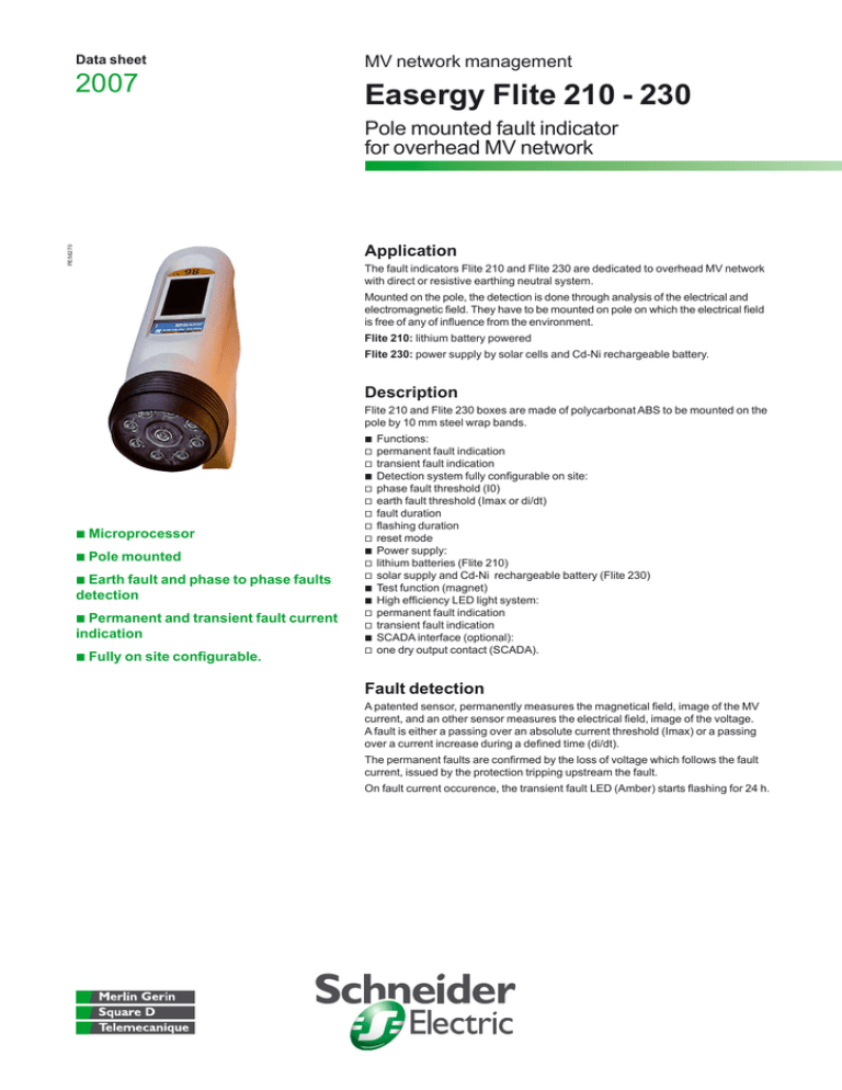
Easergy Flite 210 - 230
PE56270
Pole mounted fault indicator
for overhead MV network
Application
The fault indicators Flite 210 and Flite 230 are dedicated to overhead MV network
with direct or resistive earthing neutral system.
Mounted on the pole, the detection is done through analysis of the electrical and
electromagnetic field. They have to be mounted on pole on which the electrical field
is free of any of influence from the environment.
Flite 210: lithium battery powered
Flite 230: power supply by solar cells and Cd-Ni rechargeable battery.
Description
Flite 210 and Flite 230 boxes are made of polycarbonat ABS to be mounted on the
pole by 10 mm steel wrap bands.
b Microprocessor
b Pole mounted
b Earth fault and phase to phase faults
detection
b Permanent and transient fault current
indication
b Fully on site configurable.
b
v
v
b
v
v
v
v
v
b
v
v
b
b
v
v
b
v
Functions:
permanent fault indication
transient fault indication
Detection system fully configurable on site:
phase fault threshold (I0)
earth fault threshold (Imax or di/dt)
fault duration
flashing duration
reset mode
Power supply:
lithium batteries (Flite 210)
solar supply and Cd-Ni rechargeable battery (Flite 230)
Test function (magnet)
High efficiency LED light system:
permanent fault indication
transient fault indication
SCADA interface (optional):
one dry output contact (SCADA).
Fault detection
A patented sensor, permanently measures the magnetical field, image of the MV
current, and an other sensor measures the electrical field, image of the voltage.
A fault is either a passing over an absolute current threshold (Imax) or a passing
over a current increase during a defined time (di/dt).
The permanent faults are confirmed by the loss of voltage which follows the fault
current, issued by the protection tripping upstream the fault.
On fault current occurence, the transient fault LED (Amber) starts flashing for 24 h.
Characteristics
Application
Overhead network
Frequency
Neutral system
Fault detection (configurable)
Absolute setting
di/dt setting
dT
Temporisation
Loss of voltage validation
Inrush delay
Reset
Automatic reset on voltage recovery
Delay after power recovery
Long duration delay
Manually on the box
Light indication
Total flight flow
Flashing period
Standard flashing duration
Power supply
Power supply
Battery: standard life duration
Environment
Service temperature
Protection level (IEC 60529)
Mechanical characteristics
Dimensions
Weight
Flite 210
Flite 230
kV
Hz
4 to 69
50 and 60
Resistive or direct
4 to 69
50 and 60
Resistive or direct
A
ms
10 - 20 - 40 - 80 - 200 - 400 - 800
25% - 50% - 100% - 200%
40 - 100 - 300 - 400
10 - 20 - 40 - 80 - 200 - 400 - 800
25% - 50% - 100% - 200%
40 - 100 - 300 - 400
s
No or 5 s
3
No or 5 s
3
V/m
s
h
Level: 25
3 or 30
2 - 4 - 6 - 8 - 16
By magnet
Level: 25
3 or 30
2 - 4 - 6 - 8 - 16
By magnet
Lm
s
h
7
3
400
7
3
400
year
Lithium battery
> 10
Solar cell + Cd-Ni battery
>5
°C
– 40 to +70
IP 54
– 40 to +70
IP 54
mm
kg
300 x 150
0.8
300 x 150
0.8
References
Schneider Electric Industries SAS
89, boulevard Franklin Roosevelt
F-92506 Rueil-Malmaison Cedex
Tel: +33 (0)1 41 29 85 00
www.schneider-electric.com
www.merlin-gerin.com
C 1011039
C 1051270
C 101104
C 1051125
Flite 210
Flite 210 TS
Flite 230
Flite 230 TS
SCADA
output
b
ART.10598 © Schneider Electric Industries SAS - All rights reserved
59946
59948
59947
59949
Power supply
Battery
Solar
b
b
b
b
b
As standards, specifications and designs change from time to time, please ask for confirmation
of the information given in this publication.
This document has been printed
on ecological paper
Publishing: Schneider Electric Industries SAS
Design: Schneider Electric Industries SAS
Printing: Imprimerie du Pont de Claix/JPF - Made in France
ENMED301055EN
06-2007

