Product Bulletin
Inline Diffusers
80.1:6010
March 2013
D100194X012
Fisherr 6010, 6011, 6012, 6013,
and Whisper Disk Diffusers
Because valves can be substantial noise contributors
when controlling industrial processes, a complete line
of Fisher diffusers is offered to provide optimum noise
attenuation. A diffuser is a pressure-reducing device
that is installed downstream from the control valve.
When installed, the total pressure drop of the system
is divided across the valve and diffuser. This enables
the valve to operate at a lower pressure drop ratio,
thereby lowering the noise level generated from the
process flowing through the control valve.
installed downstream of any control valve. These
diffusers do not need to be placed adjacent to a
control valve. Multiple diffuser types are available,
providing an increased level of flexibility to meet a
range of applications. Inline diffusers are used in
steam, gas, and vapor flow applications to achieve
minimum noise generation.
Inline Diffusers
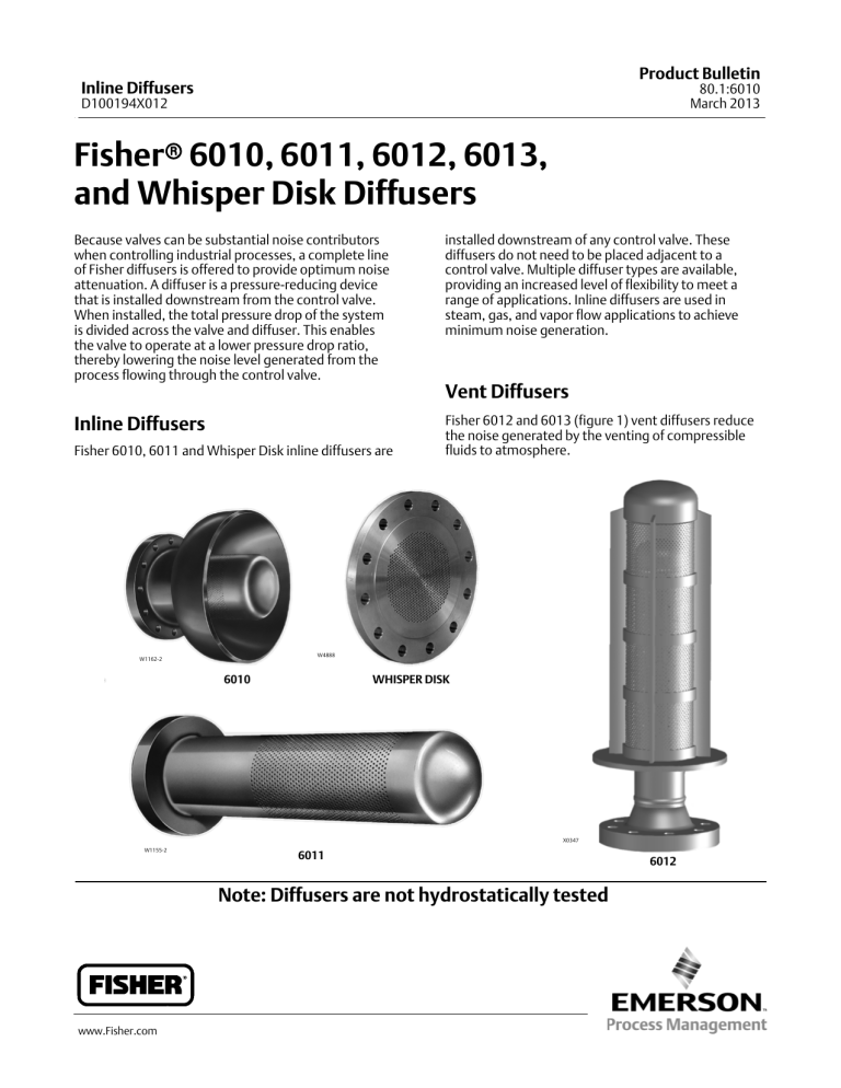
Fisher 6012 and 6013 (figure 1) vent diffusers reduce
the noise generated by the venting of compressible
fluids to atmosphere.
Fisher 6010, 6011 and Whisper Disk inline diffusers are
Vent Diffusers
W4888
W1162-2
6010
WHISPER DISK
X0347
W1155-2
6011
Note: Diffusers are not hydrostatically tested
www.Fisher.com
6012
Product Bulletin
Inline Diffusers
80.1:6010
March 2013
D100194X012
Specifications
Available Configurations
6010: Inline diffuser (with integral outlet head)
6011: Inline diffuser (pipe-style)
Whisper Disk: Inline diffuser (flat plate)
6012: Drilled-hole vent diffuser
6013: Drilled-hole vent diffuser (with outer shell)
Weights & Dimensions(1)
Sizes
6010: NPS 1 x 3 to NPS 26 x 48 (inlet x outlet)
6011: NPS 2 to NPS 30
Whisper Disk: NPS 2 to NPS 24
6012: NPS 2 to NPS 26
6013: NPS 2 to NPS 26 (outer shell NPS 4 to 36)
Design Standards
6010: See figure 2 and table 3.
6011: See figure 3 and table 5.
6012: See figure 5 and table 9.
6013: See figure 6 and table 10.
Whisper Disk: See figure 4
Diffuser wall thicknesses are designed in accordance
with the ASME Boiler and Pressure Vessel Code,
Section VIII, Division 1 and materials used are listed in
Section II, Part D
End Connections
6010: Any combination of flanged (raised-face,
ring-type joint, and flat-face) or welded end (buttweld
or socket weld)
6011: Wafer flanged
Whisper Disk: Raised-face or ring-type joint flanged
6012 and 6013: Raised-face flanged, ring-type joint
flanged, or buttweld end
End connection flanges are in compliance with ASME
B16.5 and buttweld ends are in compliance with
ASME B16.25
Contact your Emerson Process Management sales
office for availability of PED 97/23/EC compliant
materials of construction
Note
Inline and vent diffusers are not hydrostatically tested.
Materials
See table 1
1. Your Emerson Process Management sales office can determine actual weights and lengths after the diffuser has been sized for pressure and noise conditions.
Table 1. Construction Materials
DIFFUSER FLANGE
OR WHISPER DISK
DIFFUSER TUBE
DIFFUSER HEAD
CAP
_C
_F
Steel(1)
Steel (SA-105)
Grade B (SA-106)
Grade WPB (SA-234)
-29 to 427
-20 to 800
Alloy Steel(2) (1-1/4 Cr-1/2 MO)
Grade F11 (SA-182)
Grade P11 (SA-335)
Grade WP11 (SA-234)
-29 to 593
-20 to 1100
Alloy Steel(3) (2-1/4 Cr-1 MO)
Grade F22 (SA-182)
Grade P22 (SA-335)
Grade WP22 (SA-234)
-29 to 593
-20 to 1100
S31600 (316 SST)
Grade F316 (SA-182)
Grade TP316 (SA-312)
Grade WP316H (SA-403)
-198 to 649
-325 to 1200
S30400 (304 SST)
Grade F304 (SA-182)
Grade TP304 (SA-312)
Grade WP304H (SA-403)
-198 to 649
-325 to 1200
Nickel Alloy (Alloy 400)
Grade 400 (B564)
Grade 400 (B165)
Grade WPNC (B366)
-198 to 482
-325 to 900
1. Sour gas diffuser assembly can be heat treated to 22 RHC (Rockwell C) maximum hardness as required by NACE MR0175.
2. Wrought equivalent to WC6.
3. Wrought equivalent to WC9.
2
TEMPERATURE LIMITS
MATERIAL
Product Bulletin
Inline Diffusers
80.1:6010
March 2013
D100194X012
Figure 1. Control Valve and Diffuser Divide the
Overall Pressure Drop
ATMOSPHERE
Features
Versatility– The diffuser concept is used in several
unique versions, providing optimum solutions for
various applications. The diffuser need not be
installed adjacent to the control valve.
Noise Attenuation– A properly selected
diffuser-valve combination can result in up to 40
dBA noise reduction.
Total Control– A diffuser-valve combination retains
the pressure/flow control associated with a
standard control valve. Just as important, it controls
the generation of potentially damaging noise and
vibration.
Lower Life-Cycle Cost– All Fisher diffusers, both
inline and vent, are ruggedly built static devices
requiring no maintenance after installation. These
features combine to offer increased noise control at
a minimum investment.
TUBE
BAFFEL
SHELL
INTERMEDIATE
PRESSURE
ATMOSPHERIC
PRESSURE
INLET
PRESSURE
TYPICAL FISHER 6013 DIFFUSER INSTALLATION
Ordering Information
Contact your Emerson Process Management sales
office to order diffusers. All Fisher diffusers are
designed in Marshalltown, Iowa, 50158, USA. Sales
representatives should complete standard order entry
in addition to the Diffuser Engineering Form that is
available on FishWeb. Sales representatives should
also send the Diffuser Engineering Form and Customer
Data Sheet to DiffuserSpecSheets@Emerson.com.
3
Product Bulletin
Inline Diffusers
80.1:6010
March 2013
D100194X012
Fisher 6010 Inline Diffuser
Table 2. Typical Fisher 6010 Diffuser Dimensions(1)
Figure 2. Fisher 6010 Diffuser Dimensions
OPTIONAL
FLANGES TO
CUSTOMER
SPECIFICATIONS
DIFFUSER
SIZE(2)
DIAMETER
DO
OUTLET
HEAD
L2
L
30A8680-D
A2137-1A
6010
NOTE:
OVERALL DIFFUSER TUBE LENGTH MAY EXCEED FACE-TO-FACE LENGTH.
FLANGED
L
BUTTWELD
L2
APPROXIMATE
WEIGHT(4)
Do(3)
mm
Inch
mm
Inch
mm
Inch
kg
lb
1x3
1.5 x 3
2x4
2x6
2.5 x 6
152
165
203
229
229
6.00
6.50
8.00
9.00
9.00
84
89
122
148
141
3.31
3.50
4.81
5.81
5.56
76
76
102
152
152
3
3
4
6
6
1.3
1.6
2.5
4.3
5.2
2.75
3.50
5.50
9.50
11.50
3x6
3x8
4x8
6 x 12
8 x 16
229
241
279
330
381
9.00
9.50
11.00
13.00
15.00
138
151
170
205
240
5.44
5.94
6.69
8.06
9.44
152
203
203
305
406
6
8
8
12
16
7.8
10
14
33
48
17
23
31
72
105
10 x 14
10 x 16
10 x 20
12 x 24
14 x 28
16 x 32
18 x 36
356
406
457
483
483
483
508
14.00
16.00
18.00
19.00
19.00
19.00
20.00
195
246
297
319
310
297
316
7.69
9.69
11.69
12.56
12.19
11.69
12.44
356
406
508
610
711
813
914
14
16
20
24
28
32
36
73
77
93
122
249
374
443
160
170
205
270
550
824
976
20 x 36
24 x 36
508
533
20.00
21.00
310
322
12.19
12.69
914
914
36
36
536
714
1181
1573
1. Dimensions may vary to meet specific sound attenuation or piping requirements.
2. Inlet x outlet nominal pipe sizes.
3. Dimensions are nominal pipe size.
4. Weights do not include optional flanges.
Table 3. Minimum Outlet Head Size for Fisher 6010 Diffusers(1)
MAXIMUM HEAD
WALL THICKNESS
mm
Inches
INLET TUBE SIZE,
NPS
MINIMUM OUTLET HEAD(2) SIZE,
NPS
MAXIMUM HEAD
SCHEDULE
1
1
2
2.5
80
80
5.5
7.0
0.218
0.276
1.5
2
2.5
3
4
4
80
XXS
80
7.6
17.1
8.6
0.300
0.674
0.337
3
4
6
5
6
10
80
80
160
9.5
10.9
28.6
0.375
0.432
1.125
8
10
12
12
14
18
160
XS
80
33.3
12.7
23.8
1.312
0.500
0.938
14
16
18
20
20
24
80
STD only
40
26.2
9.5
17.5
1.031
0.375
0.688
20
24
26
30
20
30
12.7
15.9
0.500
0.625
1. This chart may be used to determine physical size limitations. It is not intended to be used as a guide or substitute for outlet velocity calculations or outlet sizing.
2. Larger head sizes are available on all inlet sizes.
4
Product Bulletin
Inline Diffusers
80.1:6010
March 2013
D100194X012
Fisher 6011 Inline Diffuser
Table 4. Typical Fisher 6011 Diffuser Dimensions(1)
Figure 3. Fisher 6011 Diffuser Dimensions
T
MATING
FLANGE
DIAMETER
DT
L
FLANGE FACING TO
CUSTOMER SPECIFICATION
30A8679-E
A2137-1B
6011
MAXIMUM
TUBE SIZE
DT(3,4)
APPROXIMATE
WEIGHT
DIFFUSER
SIZE(2), NPS
(MATING
FLANGE)
mm
Inch
mm
Inch
mm
Inch
kg
lb
2
3
4
6
483
635
711
1295
19
25
28
51
16
19
22
28
0.63
0.75
0.88
1.12
32
64
76
127
1.25
2.50
3
5
2.7
9
14
41
6
20
30
90
8
10
12
14
1473
1778
2134
2184
58
70
84
86
32
38
44
44
1.25
1.50
1.75
1.75
152
203
254
254
6
8
10
10
68
113
159
181
150
250
350
400
16
18
20
24
26
30
2286
2286
2286
2286
2286
2286
90
90
90
90
90
90
51
51
51
51
70
70
2.00
2.00
2.00
2.00
2.75
2.75
305
356
406
508
508
610
12
14
16
20
20
24
268
340
397
544
544
635
590
750
875
1200
1200
1400
MAXIMUM
L
T
1. Dimensions may vary to meet specific sound attenuation or piping requirements.
2. Specify mating flange size for diffuser size.
3. Heavy schedule mating flange may require smaller tube size.
4. Smaller tube sizes available for increased annular area.
Table 5. Maximum Tube Size for Fisher 6011 Diffusers(1)
MATING LINE
Mating Flange Line Size,
NPS
Maximum Schedule
Allowed
2
2
3
3
4
6
6
8
10
12
12
14
16
18
20
24
26
30
STD only
XS
STD only
160
80
80
160
120
100
160
60
80
80
80
60
XS
XS
XS
Maximum Allowable
Wall Thickness
mm
Inches
3.9
5.5
5.4
11.1
8.6
11.0
18.3
18.3
18.3
33.3
14.3
19.1
21.4
23.8
20.6
12.7
12.7
12.7
0.154
0.218
0.216
0.438
0.337
0.432
0.719
0.719
0.719
1.312
0.562
0.750
0.844
0.938
0.812
0.500
0.500
0.500
MAXIMUM 6011
TUBE SIZE,
NPS
1-1/2
1-1/4
2-1/2
2
3
5
4
6
8
8
10
10
12
14
16
20
20
24
1. This chart may be used to determine physical size limitations. It is not intended to be used as a guide or substitute for outlet velocity calculations, or outlet sizing.
5
Product Bulletin
Inline Diffusers
80.1:6010
March 2013
D100194X012
Whisper Disk Inline Diffuser
Table 6. Available Size/Pressure Class for Whisper Disk Diffusers
PRESSURE RATING(1)
SIZE,
NPS
CL150
CL300
CL400
CL600
CL900
CL1500
2
X
X
X
X
X
X
X
2-1/2
X
X
X
X
X
X
NA
3
X
X
X
X
X
X
NA
4
X
X
X
X
X
NA
NA
6
X
X
X
X
NA
NA
NA
8
X
X
X
NA
NA
NA
NA
10
X
X
NA
NA
NA
NA
NA
12
X
X
NA
NA
NA
NA
NA
14-24
X
NA
NA
NA
NA
NA
NA
CL2500
1. Ratings are for raised face flanges. Flange ratings higher than those listed may be available. Consult your Emerson Process Management sales office for higher flange ratings, other sizes, and
RTJ (ring-type joint) facing.
Table 7. Whisper Disk Maximum Allowable Cv Per Disk Size and Pressure Drop Ratio
(Pressure Drop Ratio of Disk, Not System) (1, 2)
Size, NPS
nP/P1 (psia)
Maximum of 0.60
nP/P1 (psia)
Maximum of 0.75
nP/P1 (psia)
Maximum of 0.85
nP/P1 (psia)
Maximum of 0.99
2
2-1/2
3
4
6
14
22
37
95
189
6
10
33
35
119
3
5
14
32
74
1
2
12
21
36
8
10
12
14
16
18
20
24
321
500
718
889
893
893
893
893
196
321
482
500
650
839
893
893
101
167
246
304
407
529
771
893
82
125
196
234
324
343
432
643
1. Above Cv values based on standard weight pipe upstream and downstream of disk diffuser. For heavier schedule or heavier flange maximum Cv values, consult your Emerson Process
Management sales office.
2. All maximum Cv values assume an Xt of 0.496.
6
Product Bulletin
Inline Diffusers
80.1:6010
March 2013
D100194X012
Table 8. Thickness Dimension T for Whisper Disk Diffusers
SIZE,
NPS(1)
T, MILLIMETERS
T, INCHES
Pressure Rating
Pressure Rating
CL150
CL300
CL400
CL600
CL900
CL1500
CL150
CL300
CL400
CL600
CL900
CL1500
2
2-1/2
3
4
6
19
22
24
24
25
22
25
28
32
37
32
35
38
41
48
32
35
38
44
54
44
48
44
51
---
44
48
54
54
---
0.75
0.88
0.94
0.94
1.00
0.88
1.00
1.12
1.25
1.44
1.25
1.38
1.50
1.62
1.88
1.25
1.38
1.50
1.75
2.12
1.75
1.88
1.75
2.00
---
1.75
1.88
2.12
2.12
---
8
10
12
14
16
28
30
32
35
37
41
48
51
-----
54
---------
-----------
-----------
-----------
1.12
1.19
1.25
1.38
1.44
1.62
1.88
2.00
-----
2.12
---------
-----------
-----------
-----------
18
20
24
40
43
48
-------
-------
-------
-------
-------
1.56
1.69
1.88
-------
-------
-------
-------
-------
1. For sizes and ratings not shown, contact your Emerson Process Management sales office.
Figure 4. Thickness Dimension T for Whisper Disk Diffusers
T
MATING
FLANGE
WHISPER DISK
24B0372-A
A6140
7
Product Bulletin
Inline Diffusers
80.1:6010
March 2013
D100194X012
Fisher 6012 Vent Diffuser
Table 9. Typical Fisher 6012 Diffuser Dimensions(1)
Figure 5. Fisher 6012 Vent Diffuser Dimensions
L
WEIGHT(2)
L
INLET SIZE,
NPS
mm
Inches
kg
lb
2
3
4
6
8
533
610
914
1143
1626
21.00
24.00
36.00
45.00
64.00
14
21
32
61
136
30
47
70
135
300
10
12
14
16
18
2032
2642
2743
2794
3353
80.00
104.00
108.00
110.00
132.00
206
354
372
499
782
455
780
820
1100
1725
20
3962
156.00
816
1800
1. Dimensions may vary to meet specific sound attenuation or piping requirements.
2. Weights do not include flanges.
11B2707-A
Fisher 6013 Vent Diffuser
Table 10. Typical Fisher 6013 Diffuser Dimensions(1)
Figure 6. Fisher 6013 Vent Diffuser Dimensions
L
WEIGHT(2)
L
INLET SIZE,
NPS
mm
Inches
kg
lb
2
3
4
6
8
1118
1219
1524
1829
2134
44.00
48.00
60.00
72.00
84.00
64
88
113
191
329
140
195
250
420
725
10
12
14
16
18
2743
3353
3353
3505
3962
108.00
132.00
132.00
138.00
156.00
465
748
767
984
1383
1025
1650
1690
2170
3050
20
4572
180.00
1569
3460
1. Dimensions may vary to meet specific sound attenuation or piping requirements.
2. Weights do not include flanges.
11B2707-A
Table 11. Minimum Shell Size for Fisher 6013 Diffuser
Diffuser
Inlet Size
mm
51
76
102
152
203
254
305
356
406
457
NPS
2
3
4
6
8
10
12
14
16
18
508
20
Nominal
Shell Size
mm
203
254
305
356
406
508
610
610
711
762
813
Inches
8
10
12
14
16
20
24
24
28
30
32
Neither Emerson, Emerson Process Management, nor any of their affiliated entities assumes responsibility for the selection, use or maintenance
of any product. Responsibility for proper selection, use, and maintenance of any product remains solely with the purchaser and end user.
Fisher is a mark owned by one of the companies in the Emerson Process Management business unit of Emerson Electric Co. Emerson Process Management,
Emerson, and the Emerson logo are trademarks and service marks of Emerson Electric Co. All other marks are the property of their respective owners.
The contents of this publication are presented for informational purposes only, and while every effort has been made to ensure their accuracy, they are not
to be construed as warranties or guarantees, express or implied, regarding the products or services described herein or their use or applicability. All sales are
governed by our terms and conditions, which are available upon request. We reserve the right to modify or improve the designs or specifications of such
products at any time without notice.
Emerson Process Management
Marshalltown, Iowa 50158 USA
Sorocaba, 18087 Brazil
Chatham, Kent ME4 4QZ UK
Dubai, United Arab Emirates
Singapore 128461 Singapore
www.Fisher.com
E
8 1987, 2013 Fisher Controls International LLC. All rights reserved


