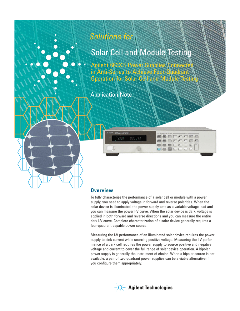
Solutions for Solar Cell and Module Testing 2

Solutions for
Solar Cell and Module Testing
Agilent 663XB Power Supplies Connected in Anti-Series to Achieve Four-Quadrant
Operation for Solar Cell and Module Testing
Application Note
Overview
To fully characterize the performance of a solar cell or module with a power supply, you need to apply voltage in forward and reverse polarities. When the solar device is illuminated, the power supply acts as a variable voltage load and you can measure the power I-V curve. When the solar device is dark, voltage is applied in both forward and reverse directions and you can measure the entire dark I-V curve. Complete characterization of a solar device generally requires a four-quadrant-capable power source.
Measuring the I-V performance of an illuminated solar device requires the power supply to sink current while sourcing positive voltage. Measuring the I-V performance of a dark cell requires the power supply to source positive and negative voltage and current to cover the full range of solar device operation. A bipolar power supply is generally the instrument of choice. When a bipolar source is not available, a pair of two-quadrant power supplies can be a viable alternative if you configure them appropriately.
Problem
Obtaining an uninterrupted test voltage that is adjustable over a range that encompasses positive and negative voltage and current values without a bipolar power supply can be a challenge. The use of a single- or two-quadrant power supply with a polarity reversing relay or switch matrix creates a discontinuity at or near zero volts that may not be acceptable.
With the solar cell illuminated, power supply 1 is programmed from zero volts to Voc, and it will sink current generated by the solar cell. Power supply 2 is programmed to and held at zero volts. When the device is dark and the total voltage on the cell is greater than zero, power supply 1 will source current and power supply 2 will sink current. When the device is dark and the total voltage on the cell is less than zero, power supply 2 will source current and power supply 1 will sink current.
Solution
Obtaining an uninterrupted voltage ranging from beyond a cell or module’s open circuit voltage to full reverse polarity can be achieved with a pair of two-quadrant power supplies connected in anti-series. The negative terminals of the supplies are connected together and the positive terminals of both are connected to the solar device under test. Figure
1 depicts two Agilent 6631B power supplies in an arrangement for testing the performance of a solar cell. The positive terminal of power supply 1 is connected to the positive terminal of the solar cell. The positive terminal of power supply 2 is connected to the negative terminal of the solar cell.
Each power supply must be capable of sourcing and sinking its full rated current. When you connect them in an anti-series configuration, the combination offers operation in four quadrants. When power supply 1 sources current, power supply 2 will sink current. Conversely, when power supply 2 sources current, power supply 1 will sink current. The current-sinking capability of each power supply must be equal to or greater than the sourcing capability of the other to obtain the full rated operating range.
6631B power supply 1
+s + -s
-
-S
+s
-
+ -
-S
-s
To ensure that the voltage applied to the solar cell is accurate, you must connect the sense leads appropriately. Connect the positive sense leads of each power supply to the solar cell where you plan to measure the voltage. Connect the negative sense leads to a common location, either on the lead that couples the negative outputs or on the negative terminal of one of the supplies. Figure 1 shows the negative sense leads attached to a point midway on the lead that connects the negative terminals of both supplies. Using remote sensing eliminates the voltage drops on the lead wires and greatly improves your accuracy.
+
Solar cell
-
6631B power supply 2
Figure 1: Two 6631B two-quadrant power supplies connected in anti-series
2
Process
An example test sequence is outlined below.
Test steps are executed in one continuous sequence to obtain:
1. Illuminated I-V curve
2. Dark I-V curve (forward bias region)
3. Dark I-V curve (reverse bias region)
Program power supply 1 and 2 voltages to obtain the required solar cell voltages in forward and reverse polarities. To measure the I-V curve of a solar cell when it is illuminated, incrementally increase the voltage of power supply 1 to Voc. To measure the dark I-V curve, use power supply 1 at Voc and incrementally increase the voltage of power supply 2 to offset the voltage of power supply 1 until you reach the required reverse bias level.
Isc
Solar cell
Illuminated
Power I-V curve
0
Dark
Dark I-V curve
0
Solar cell
Cell voltage transition through zero
Voc
0
Cell voltage is power supply 1 minus power supply 2 voltage
Max. reverse polarity = power supply 2minus power supply 1 voltage
Power supply 1
Power supply 2
Voc (or higher)
Required max reverse cell voltage plus power supply 1 voltage
0
Time
Figure 2. Solar cell voltage and current and the voltages of power supplies 1 and 2 plotted against time
3
Technical Specifications
Test step 1: Illuminated cell I-V curve measurement (power quadrant)
Solar device and power supply status
• Solar device sources current
• Power supply 1 sinks current
• Power supply 2 sources current
(output maintained at zero volts)
Setup:
A. Program power supply 1 to 0 V and program current limit to beyond Isc
B. Program power supply 2 to zero volts and program its current limit to beyond Isc
Procedure:
1. Illuminate the solar device
2. Program power supply 1 to
increase its voltage from zero to
Voc in small increments and
remain at Voc after illumination is
extinguished.
3. Keep power supply 2
programmed to 0 V
Test step 2: Dark I-V curve measurement (forward bias region)
Solar device and power supply status
• Current flows into the positive terminal of the solar cell
• Power supply 1 sources current
• Power supply 2 sinks current
Setup:
A. Power supply 1 voltage level
begins at Voc
Procedure:
1) Program power supply 2 to
increase its voltage in small
increments to offset the voltage of
Power Supply 1 until the net volt-
age across the solar cell is zero.
Test step 3: Dark I-V curve measurement (reverse bias region)
Solar device and power supply status
• Current flows into the negative terminal of the solar cell
• Power supply 1 sinks current
• Power supply 2 sources current
Procedure: (continuation from test step 2)
2) The test continues with the increase of the voltage of power supply 2 in small increments to obtain the desired net negative voltage that reverse biases the solar cell.
3) When the reverse bias test is completed, both power supplies are programmed to zero volts.
Isc
Voltage (V)
0
0
Figure 4: Dark I-V curve measurement
(forward bias region)
0
0
Voltage (V)
Figure 5. Dark I-V curve measurement
(reverse bias region)
0
0
Voltage (V)
Figure 3: Illuminated cell I-V curve measurement (power quadrant)
Voc
4
Alternative Test Sequences
Other test voltage sequences are possible. For example, if you want to perform both illuminated and dark cell tests, an alternative approach for test step 2 is to program the voltage of power supply 1 to decrease gradually to zero after you have completed test step 1. With the cell in darkness, you can obtain the I-V characteristic in the forward region, as depicted in test step 2. When power supply 1 voltage reaches zero, you can increase power supply 2 voltage to reverse bias the cell to obtain the I-V characteristic depicted in test step 3.
Using either approach to solar cell testing will result in a transition from forward to reverse bias through zero volts without the delay and associated circuit interruption associated with polarity reversal relays and switches. If it is absolutely necessary to avoid all discontinuities as the cell is reverse biased, it is important to note that the second approach may introduce a small discontinuity near zero volts due to programming offsets.
Conclusion
Successfully configuring power supplies in anti-series for testing illuminated and dark solar cells requires that each supply is capable of sinking the current that will be sourced by the other. Power supply 1 in the configuration must be capable of sinking, and power supply 2 must be capable of sourcing, the current produced by the solar cell under illumination.
Related Agilent Literature Publication Type
6631B, 32B, 33B & 34B Power Supplies Catalog pages
Solar Cell and Module Testing Application Note
Pub number
5989-8959EN
5990-3263EN
5
www.agilent.com
Agilent Email Updates www.agilent.com/find/emailupdates
Get the latest information on the products and applications you select.
Agilent Direct www.agilent.com/find/agilentdirect
Quickly choose and use your test equipment solutions with confidence.
www.lxistandard.org
LXI is the LAN-based successor to
GPIB, providing faster, more efficient connectivity. Agilent is a founding member of the LXI consortium.
Remove
all
doubt
Our repair and calibration services will get your equipment back to you, performing like new, when promised. You will get full value out of your Agilent equipment throughout its lifetime. Your equipment will be serviced by Agilent-trained technicians using the latest factory calibration procedures, automated repair diagnostics and genuine parts.
You will always have the utmost confidence in your measurements.
For information regarding self maintenance of this product, please contact your Agilent office.
Agilent offers a wide range of additional expert test and measurement services for your equipment, including initial start-up assistance, onsite education and training, as well as design, system integration, and project management.
For more information on repair and calibration services, go to: www.agilent.com/find/removealldoubt
For more information on Agilent
Technologies’ products, applications or services, please contact your local
Agilent office. The complete list is available at: www.agilent.com/find/contactus
Americas
Latin America 305 269 7500
United States (800) 829-4444
Asia Pacific
Australia
China
Hong Kong
India
Japan
Korea
Malaysia
Singapore
Taiwan
Thailand
1 800 629 485
800 810 0189
800 938 693
1 800 112 929
0120 (421) 345
080 769 0800
1 800 888 848
1 800 375 8100
0800 047 866
1 800 226 008
Europe & Middle East
Austria
Belgium
Denmark
Finland
France
01 36027 71571
32 (0) 2 404 93 40
45 70 13 15 15
358 (0) 10 855 2100
0825 010 700*
Product specifications and descriptions in this document subject to change without notice.
Germany
Ireland
Israel
Italy
Netherlands
07031 464 6333
1890 924 204
972-3-9288-504/544
39 02 92 60 8484
31 (0) 20 547 2111
Spain
Sweden
34 (91) 631 3300
0200-88 22 55
Switzerland 0800 80 53 53
United Kingdom 44 (0) 118 9276201
Other European Countries: www.agilent.com/find/contactus
Revised: March 24, 2009
© Agilent Technologies, Inc. 2009
Printed in USA, July 29, 2009
5990-3949EN


