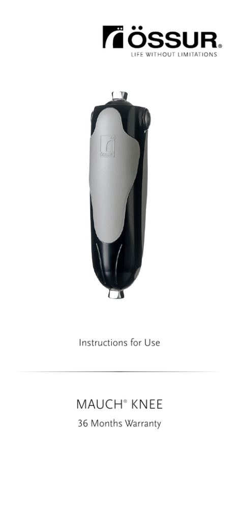
Mauch Knee Instructions for use
advertisement

Instructions for Use MAUCH KNEE ® 36 Months Warranty 58.0 mm 85.0 mm (29⁄32 in) (311⁄32 in) 248.0 mm (94⁄5 in) 6.0 mm (¼ in) 202.7 mm (8 in) 73.0 mm (27⁄8 in) 220.0 mm (821⁄32 in) 1 Socket bisection 2 Alignment reference line Pivot axis 3 Minimum Medium Maximum 4 Minimum Medium Maximum 2 5 Maximum Stance Resistance Adjust with 2mm Hex Key Minimum Stance Resistance 6 Engaged Manual Lock or Swing Only Disengaged Manual Lock or Swing Only 7 8 Swing Only Locked 3 ENGLISH Product No.: Description: MKN71360 KNEE PACKAGE KIT (SNS) MKN71361 KNEE PACKAGE KIT (SNS – LOW RESISTANCE) MKN71362 KNEE PACKAGE KIT (SWING) MKN71363 KNEE PACKAGE KIT (SNS – HIGH STANCE RESISTANCE) APPLICATION The Mauch® Knee is exclusively used for lower limb prosthetic fittings. TECHNICAL SPECIFICATIONS • Maximum weight 136kg (300lbs) • Net weight = 1140g (2.51lbs) • 115° knee flexion available FUNCTION & DESIGN • Single-axis hydraulic knee system with swing control (S) or swing and stance control (SNS). • Designed for multispeed ambulation. • Yielding stance control (with SNS package). • Mode selector switch allows for manual locking and free swing functions (with SNS package). • The frame is constructed of aircraft-grade aluminum optimized for strength. • Side load spherical bearings at knee axis and high-tech bearings ensure: –– Smoother motion –– Reduced play –– Increased durability CAUTION Using a 4-hole adapter for a long residual limb can limit knee flexion, because it may hit the knee frame and cover before the full range of knee flexion is achieved. FOR LONG RESIDUAL LIMBS, ÖSSUR RECOMMENDS: • Össur 3-Prong Socket Adapter, A-114030. • Össur 4-Prong Socket Adapter, A-114040. ALIGNMENT: (Figure 2) The alignment reference line is equal to the weight line. 1. Alignment Reference Line (Socket Bisection). 2. Knee Axis Reference Point. • Establish a vertical pylon. • Establish the knee center height. • Establish the appropriate socket angles. 5 degrees of socket flexion is recommended. • Position the socket so that the alignment reference line bisects the lateral wall at the ischial level of the socket and falls through or slightly posterior to the knee axis. • Establish the correct length of the prosthesis. 4 NOTES: • The pyramid is shifted 6mm in an anterior direction from the knee axis. • If the weight line is too far anterior to the knee axis, the knee may require more effort to create a hyperextension moment that will disengage the stance control and allow for fluid initiation of the knee flexion. • Premature knee flexion may result from a weight line position too posterior to the knee axis. SWING PHASE The Mauch system is designed to provide variable hydraulic resistance to flexion and extension during swing phase based on changes in the user’s walking speed. The resistance settings can be adjusted by rotating the cap atop the control cylinder. FLEXION RESISTANCE: (Figure 3) Turn the cap relative to the indicator mark for flexion. 1. Extreme left arrow indicates minimum resistance. 2. Arrow at “A” indicates medium resistance. 3. Extreme right arrow indicates maximum resistance. Remember the selected value of flexion resistance. EXTENSION RESISTANCE: (Figure 4) Turn the cap to either extreme to move the indicator mark. • 1 is minimum resistance. • 5–6 is medium resistance. • 10 is maximum resistance. Make sure you reset the correct value of flexion resistance before asking the patient to walk. STANCE PHASE: (Figure 5) The Mauch stance control system is designed to provide hydraulic yielding resistance to knee flexion when the prosthesis is loaded. This assists the user in descending stairs foot over foot and in stumble recovery. The stance resistance or yielding rate can be adjusted using the screw near the U-Lever on the piston rod. 1. Full clockwise rotation sets the minimum yielding rate (maximum stance resistance). 2. One-third rotation counterclockwise sets the maximum yield rate (minimum stance resistance). Do not exceed one-third rotation. SPECIALIZED MODES OF OPERATION U-Lever (Mode Selector Switch: (Figure 6) The Mauch system is designed to provide the user with a manual lock and a Swing Only mode of operation. These functions are engaged and disengaged through the U-Lever or mode selection switch located near the top of the piston rod. The manual lock may be useful when the user requires additional safety. Swing Only mode is useful during rowing, running, or cycling activities. 1. Manual Lock or Swing Only mode engaged. U-Lever in up position. 2. Manual Lock or Swing Only mode disengaged. U-Lever in down position. 5 PROCEDURE FOR ENGAGING SWING ONLY MODE: (Figure 7) • Hyperextend the knee. • Raise the U-Lever. • Stance resistance is eliminated. PROCEDURE FOR ENGAGING MANUAL LOCK: (Figure 8) • Do not hyperextend. • Raise the U-Lever. • Unit is locked against flexion. MAINTENANCE • Cylinders cannot be replaced in the field. For cylinder replacement and/or repairs, send the knee joint in for service. • Knee joints must be stored upright. Storing cylinders or knee joints on their side will cause the cylinder to draw in air. Air can be bled from the system by engaging Swing Only mode and cycling the cylinder until all of the air has been eliminated. • Clean the extension stops regularly to prevent dirt buildup that may compromise the cylinder release. Use a blunt instrument and be careful not to scratch the contact areas. Do Not disassemble the knee joint or attempt your own repairs. If a problem should arise, send the knee joint in for service. CLEANING Wipe the knee with a soft cloth moistened with a small amount of kerosene. Do not use compressed air to clean the knee. Air will force pollutants into the bearings which may cause malfunctions and early deterioration. Do not use any solvents stronger than kerosene. Do not immerse the whole knee or pour solvent over the knee, which would damage the bearings and seals. COSMETICS Do not use talcum powder to eliminate noise in the cosmetic cover. It reduces lubrication, which may lead to malfunctions and early deterioration of mechanical parts. Use silicone spray instead. WARRANTY Össur offers 36 months limited warranty on manufacturing faults. CAUTION! Avoid placing hands or fingers near moving joints. MAUCH® KNEE ACCESSORIES Product No: Description: MKA01361 KNEE BALL, SCREW, BTN HEAD MKA01362 COVER, FRONT MKA01363 COVER, REAR MKA01364 PLUG, SIDE MKA01365 EXTENSION STOP, SOFT MKA01366 EXTENSION STOP, HARD 6 LIABILITY The manufacturer recommends using the device only under the specified conditions and for the intended purposes. The device must be maintained according to the instructions for use. The manufacturer is not liable for damage caused by component combinations that were not authorized by the manufacturer. CE CONFORMITY This device meets the requirements of the 93/42/EEC guidelines for medical devices. This device has been classified as a class I device according to the classification criteria outlined in appendix IX of the guideline. COMPLIANCE This component has been tested according to ISO 10328 standard to three million load cycles. Depending on the amputee’s activity this corresponds to a duration of use of three to five years. We recommend carrying out regular yearly safety checks ISO 10328 - P6 - 136 kg *) *) Body mass limit not to be exceed! For specific conditions and limitations of use see manufacturer’s written instructions on intended use! EN – Caution:Össur products and components are designed and tested according to the applicable official standards or an in-house defined standard when no official standard applies. Compatibility and compliance with these standard is achieved only when Össur products are used with other recommended Össur components. If un-usual movement or product wear is detected in a structural part of a device at any time, the patient should be instructed to immediately discontinue use of the device and consult his/ her clinical specialist. This product has been designed and tested based on single patient usage. This device should NOT be used by multiple patients. If any problems occur with the use of this product, immediately contact your medical professional. 7 Össur Americas 27051 Towne Centre Drive Foothill Ranch, CA 92610, USA Tel: +1 (949) 382 3883 Tel: +1 800 233 6263 ossurusa@ossur.com Össur Head Office Grjótháls 5 110 Reykjavík, Iceland Tel: +354 515 1300 Fax: +354 515 1366 mail@ossur.com WWW.OSSUR.COM ©Copyright Össur 2016 IFU 0610 1108_002 Rev. 3


