Aerospace
Fluid Conveyance
LJ11 and J11 Joints
LJ11 and J11 Joints
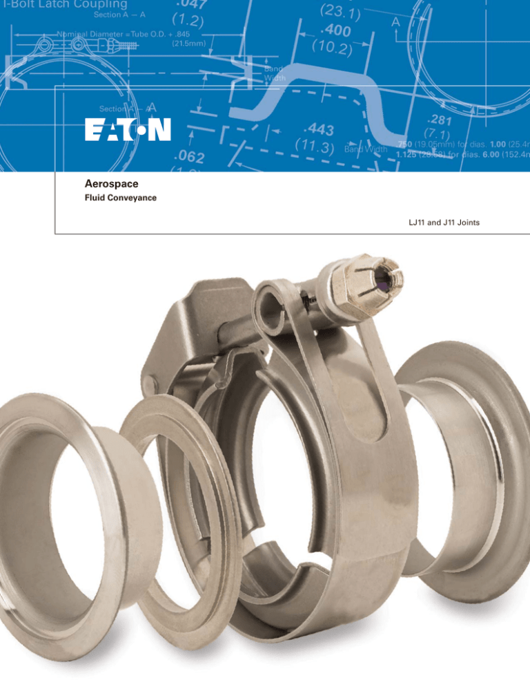
LJ11 and J11 Joints were designed primarily to join standard tubing for fuel, hot air and gas systems. The substitution of couplings
other than the coupling part numbers specified for each joint can
seriously impair the effectiveness of the joint. Although these
joints are basically the same configurations, the LJ11 flange skirts
are lighter, and the gasket is thinner except at the sealing point.
Therefore, the LJ11 Joint should be used when weight saving
is an important factor. The J11 Joint is a heavier joint with a high
safety factor.
Joint consists of one coupling, two flanges and an all-metal gasket.
Quick Coupler Latch can be connected or disconnected without
removal of nut.
LJ11 Joint is available with T-Bolt
Latch only. This latch is also used
on the large sizes of the J11 Joint.
LJ11 and J11 Joint Specifications and Dimensions
Quick Coupler Latch Coupling
Quick Coupler Latch
Trunnion
Lock Nut
T-Bolt
Retainer
Section A — A
Nominal Diameter = Tube O.D. + .845
(21.5mm)
Gap
A
Band
Width
A
Section A — A
Band
Band Width
.750 (19.05mm) for dias. 1.00 (25.4mm) through 2.75 (69.85mm)
.875 (22.23mm) for dias. 3.00 (76.2mm) through 5.50 (139.7)
T-bolt Latch Coupling
Joint
1.562 ± .125
(39.7mm) (3.2mm) Coupling
Gasket
Flange
A
A
Flange
Tube O.D.
+ .715
Tube (18.2mm)
O.D.
Band Width
2
.750 (19.05mm) for dias. 1.00 (25.4mm) through 5.00 (127mm)
1.125 (28.58) for dias. 6.00 (152.4mm) through 9.00 (228.66mm)
EATON CORPORATION Aerospace TF100-30 March 2007
inches in boldface; mm in lightface
LJ11 and J11 Joints — How To Order
Order By Component Part Numbers
One coupling, one gasket and two flanges are required to make a
complete joint. (T-Bolt and nut are furnished with coupling).
Flange skirt thickness code must be added to complete the
Flange Part Number, and gasket material code must be added to
complete the Gasket Part Number.
Sample Flange Part No.: 16933-100-6 (one inch dia. for J11 Joint
with .050 skirt thickness).
Sample Gasket Part No.: 17189-400-N (four inch dia. for J11
Joint with nickel material).
Replacement T-Bolts can be ordered for Quick Coupler Latches
only. They cannot be replaced on T-Bolt Latches. Last dash number indicates T-Bolt length in hundredths inches.
Tolerances on recommended torque are ±10%.
Gasket
Flange
.065
for dias. 1.00 (25.4 mm)
(1.7 mm) through 5.50 (139.7 mm)
.065
(1.7 mm)
Tube O.D.
+ .335
(8.5 mm)
.250 (6.4mm)
± .062 (1.6mm)
.110
for dias. 6.00 (25.4 mm)
(2.8 mm) through 9.00 (139.7 mm)
J11
Gasket
LJ11
Gasket
Tube O.D.
+ .164
(4.2 mm)
.750 ± .062
(19.1mm) (1.6 mm)
Tube O.D. Tube O.D.
+ .355
+ .015
(.4 mm) (8.5 mm)
Gasket Material
Temperature
Material Ordering Code
Aluminum
+ 500ºF
+ 260ºC
-A
Copper (Nickel Plated)
+ 750ºF
+ 399ºC
-C
Nickel
+ 1000ºF
+ 538ºC
-N
If a joint is disassembled after service operations, a new gasket should be used
when reassembled to ensure maximum sealing efficiency of the joint.
Skirt Thickness
Tube O.D. = .335 (8.5 mm)
Tube Size O.D.
Skirt Thickness
+ .005
(.030)—.010
*For LJ11 available in -3 only. +127
(.762) — .254
1.00 — 5.50
25.4 — 139.7
Ordering Code
-3*
1.00—9.00
25.4—228.6
(.050)±.010
(1.27)±2.54
-6
6.00—9.00
152.4—228.6
(.080)±.010
(2.03)±.254
-6
Inches in bold face type
Millimeters in light face type
EATON CORPORATION Aerospace TF100-30 March 2007
3
Performance Ratings for LJ11 and J11 Joints
The two principal types of loading experienced in this type of
joint are pressure and bending. The chart shown at the left is designed to help you determine the ability of the LJ11 or J11 Joint
to withstand a given load or combination of loads.
Bending Moment and Pressure
Tube O.D. (mm)
25.4
50.8
76.2
101.6
127
152.4 177.8
4000
(275.6)
203.2 228.6
24,000
(2702.7)
Step 1. If there is only one type of loading, the joint capability
may be easily determined. Draw a vertical line upward from the
joint size on the bottom scale until it intersects the appropriate
curve for joint* and type of loading.
3000
(206.7)
18,000
(2027.0)
2000
(137.8)
12,000
(1351.4)
Step 2. Draw a horizontal line from this intersection to the appropriate loading scale and read load rating. Adjust for temperature conditions by multiplying with the correction factor.
Compare this with your design load to determine suitability of
the joint.
Step 3. If a combined loading exists (bending and pressure)
determine joint capabilities for each load separately as in Steps 1
and 2 above.
6,000
(675.7)
1000
(68.9)
1
3
2
5
6
4
Tube O.D. (inches)
7
8
Step 4. Divide load rating into actual load condition for each type
of loading, and express answer as a percent. Add percentage of
load rating for each type of loading. If your answer is less than
100%, the difference represents your safety margin.
9
*If joint weight is a consideration, it is recommended that the LJ11 be checked against
the applied conditions first. If the margin of safety is not satisfactory, then steps 1
through 4 may be repeated using the J11 curves.
Code: Pressure and Bending
LJ11 Bending
J11 Bending
LJ11 Pressure
J11 Pressure
Example:
3.00 dia. joint to operate at 200º F.
300 psi proof pressure
2000 lb in. bending movement
Chart values apply up to 500 º F.
At 1000ºF reduce rated values by 50%
Temperature
+ 70º F
+21.1ºC
+200ºF
+93ºC
+400ºF
+204ºC
+500ºF
+260ºC
+600ºF
+316ºC
+800ºF
+427ºC
Correction
1.00
.88
.76
.73
.70
.63
Steps 1–3.
Rated loads for LJ11 are as follows:
642 psi proof pressure @200ºF.
4400 lb in. bending moment @200ºF.
Step 4.
300 = 46.7% of pressure load rating
642
2000 = 45.4% of bending load rating
4400
Loads are 92.1% of joint capacity
4
EATON CORPORATION Aerospace TF100-30 March 2007
LJ11 Joints
Inches, lbs. and lb. - in. in bold face type
Millimeters, kg. and N-m in light face type
Coupling
Flange
Gasket
Weight each (lbs)
T-Bolt Latch
T-Bolt*
Tube
Size
O.D.
Part
Number
Weight
each
Radius
Max.
Part Number
And Length
1.00
25.4
18276-100
.177
.080
2.093
.949
1.25
31.37
18276-125
.196
.088
1.50
38.1
18276-150
1.75
44.45
Thread
Copper
Recommended
Torque
Part
Number
Skirt Thickness Code
(Specify One)
Weight
Each
Part
Number
Material
Code
(Specify
One)
* -200
50
5.65
16933-100
-3
.050
.022
24346-100
-A
-C
-N
.008
.003
.033
.014
2.187
.992
* -200
50
5.65
16933-125
-3
.058
.026
24346-125
-A
-C
-N
.010
.004
.038
.017
.217
.098
2.531
1.148
* -250
80
9.04
16933-150
-3
.071
.032
24346-150
-A
-C
-N
.012
.005
.045
.020
18276-175
.250
.113
2.625
1.190
* -250
80
9.04
16933-175
-3
.083
.037
24346-175
-A
-C
-N
.014
.063
.050
.022
2.00
50.8
18276-200
.348
.158
2.687
1.218
* -250
80
9.04
16933-200
-3
.094
.042
24346-200
-A
-C
-N
.016
.007
.056
.025
2.25
57.15
18276-225
.370
.167
3.093
1.402
* -275
115
12.99
16933-225
-3
.103
.046
24346-225
-A
-C
-N
.018
.008
.051
.023
2.50
63.5
18276-250
.387
.171
3.125
1.417
* -275
115
12.99
16933-250
-3
.113
.051
24346-250
-A
-C
-N
.020
.009
.067
.030
2.75
69.85
18276-275
.415
.190
3.400
1.542
* -300
115
12.99
16933-275
-3
.124
.056
24346-275
-A
-C
-N
.022
.010
.074
.033
3.00
76.2
18276-300
.570
.258
3.562
1.615
* -300
115
12.99
16933-300
-3
.137
.062
24346-300
-A
-C
-N
.024
.011
.078
.035
3.50
88.9
18276-350
.624
.283
3.593
1.629
* -300
165
18.64
16933-350
-3
.158
.071
24346-350
-A
-C
-N
.028
.012
.091
.041
4.00
10.16
18276-400
.688
.312
3.781
1.715
* -300
165
18.64
16933-400
-3
.180
.081
24346-400
-A
-C
-N
.032
.014
.102
.046
4.50
114.3
18276-450
.752
.341
4.000
1.814
* -300
165
18.64
16933-450
-3
.215
.079
24346-450
-A
-C
-N
.036
.016
.114
.051
5.00
127
18276-500
.825
.374
4.250
1.927
* -300
165
18.64
16933-500
-3
.223
.101
24346-500
-A
-C
-N
.038
.017
.126
.057
10-32
UNJF
-3A
¼ - 28
UNJF
-3A
Alum.
or Nickel
* Replacement T-Bolts can be ordered for Quick Coupler Latches only. They can not be replaced on T-Bolt Latches. Last dash number indicates T-Bolt length in hundredths
inches.
EATON CORPORATION Aerospace TF100-30 March 2007
5
J11 Joints
Inches in bold face type
Millimeters in light face type
Coupling
Flange
Gasket
Weight each (lbs)
T-Bolt Latch
Quick Coupler Latch
T-Bolt*
Tube
Size
O.D.
Part Number
Weight
each
Radius
Max.
Part Number
And Length
1.00
25.4
24502-100
.277
.125
2.125
.963
1.25
31.37
24502-125
.293
.132
1.50
38.1
24502-150
1.75
44.45
24502-175
2.00
50.8
Thread
Copper
Recommended
Torque
Part
Number
Skirt Thickness Code
(Specify One)
Weight
Each
Part
Number
Material
Code
(Specify
One)
18462-75-250
70
7.91
16933-100
-3
-6
.061 †
.027
17189-100
-A
-C
-N
.012
.005
.039
.017
2.187
.992
18462-75-250
70
7.91
16933-125
-3
-6
.075 †
.034
17189-125
-A
-C
-N
.015
.006
.050
.022
.325
.147
2.500
1.133
18289-75-250
100
11.32
16933-150
-3
-6
.089 †
.040
17189-150
-A
-C
-N
.017
.007
.058
.026
.344
.156
2.562
1.162
18289-75-250
100
11.32
16933-175
-3
-6
.100 †
.045
17189-175
-A
-C
-N
.020
.009
.070
.031
24502-200
.372
2.875
1.304
18289-75-275
130
14.69
16933-200
-3
-6
.119 †
.053
17189-200
-A
-C
-N
.022
.010
.073
.033
2.25
57.15
24502-225
.387
.175
2.937
1.332
18289-75-275
130
14.69
16933-225
-3
-6
.128 †
.058
17189-225
-A
-C
-N
.024
.011
.087
.039
2.50
63.5
24502-250
.402
.182
3.062
1.388
18289-75-275
130
14.69
16933-250
-3
-6
.144 †
.065
17189-250
-A
-C
-N
.028
.012
.098
.044
2.75
69.85
24502-275
.433
.196
3.187
1.445
18289-75-275
130
14.69
16933-275
-3
-6
.156 †
.070
17189-275
-A
-C
-N
.031
.014
.110
.049
3.00
76.2
24503-300
.775
.351
3.687
1.672
18289-75-350
220
24.86
16933-300
-3
-6
.172 †
.078
17189-300
-A
-C
-N
.035
.015
.112
.050
3.50
88.9
24503-350
.835
.378
3.875
1.757
18448-88-350
220
24.86
16933-350
-3
-6
.208 †
.094
17189-350
-A
-C
-N
.037
.016
.120
.054
4.00
10.16
24503-400
.895
.405
4.062
1.842
18448-88-350
220
24.86
16933-400
-3
-6
.226 †
.102
17189-400
-A
-C
-N
.043
.019
.147
.066
4.50
114.3
24503-450
.960
.435
4.250
1.927
18448-88-350
240
27.12
16933-450
-3
-6
.268 †
.121
17189-450
-A
-C
-N
.048
.021
.170
.077
5.00
127
24503-500
1.030
.467
4.437
2.012
18448-88-350
240
27.12
16933-500
-3
-6
.290 †
.131
17189-500
-A
-C
-N
.053
.024
.180
.081
5.50
139.7
24503-550
1.080
.488
4.625
2.097
18448-88-350
240
27.12
16933-550
-3
-6
.320 †
.145
17189-550
-A
-C
-N
.059
.026
.210
.095
6.00
152.4
24504-600
1.633
.740
5.125
2.324
* -400
280
31.64
24249-600
-6
-8
.449 †
.203
24189-600
-A
-C
-N
.090
.040
.317
.143
7.00
177.8
24504-700
1.793
.813
5.500
2.494
* -400
280
31.64
24249-700
-6
-8
.507 †
.229
24189-700
-A
-C
-N
.107
.048
.386
.175
8.00
203.2
24504-800
2.005
.910
5.937
2.692
* -400
300
33.90
24249-800
-6
-8
.565 †
.256
24189-800
-A
-C
-N
.125
.056
.432
.195
9.00
228.6
24504-900
2.190
.993
6.375
2.891
* -400
300
33.90
24249-900
-6
-8
.623 †
.282
24189-900
-A
-C
-N
.140
.063
.477
.216
¼-28
UNJF
-3A
5/16-24
UNJF
-3A
Alum.
or Nickel
* Replacement T-Bolts can be ordered for Quick Coupler Latches only. They can not be replaced on T-Bolt Latches. Last dash number indicates T-Bolt length in hundredths
inches.
† Weight is for largest Flange size
6
EATON CORPORATION Aerospace TF100-30 March 2007
Assembly of LJ11 and J11 Joints To Machined Flange
Inches in bold face type
Millimeters in light face type
Tube
Size
O.D.
Part
Number
Special Gasket Material
Code (Specify One Only)
A Max
L Min.
Tube
Size
O.D.
Part
Number
Special Gasket
Material Code
(Specify One
Only)
A Max
L Min
1.00
25.4
24096-100 -A
-C
-N
1.135
.514
.515
.233
3.50
88.9
24096-350
-A
-C
-N
3.635
1.648
.593
.268
1.25
31.37
24096-125 -A
-C
-N
1.385
.628
.515
.233
4.00
10.16
24096-400
-A
-C
-N
4.135
1.875
.593
.268
1.50
38.1
24096-150 -A
-C
-N
1.635
.741
.515
.233
4.50
114.3
24096-450
-A
-C
-N
4.635
2.102
.593
.268
1.75
44.45
24096-175 -A
-C
-N
1.885
.855
.515
.233
5.00
127.00
24096-500
-A
-C
-N
5.135
2.329
.593
.268
2.00
50.8
24096-200 -A
-C
-N
2.135
.968
.515
.233
5.50
139.7
24096-550
-A
-C
-N
5.635
2.555
.593
.268
2.25
57.15
24096-225 -A
-C
-N
2.385
1.081
.515
.233
6.00
152.4
24096-600
-A
-C
-N
6.170
2.798
.718
.325
2.50
63.5
24096-250 -A
-C
-N
2.635
1.195
.515
.233
7.00
177.8
24096-700
-A
-C
-N
7.170
3.252
.718
.325
2.75
69.85
24096-275 -A
-C
-N
2.885
1.308
.515
.233
8.00
203.2
24096-800
-A
-C
-N
8.170
3.705
.718
.325
3.00
76.2
24096-300 -A
-C
-N
3.135
1.422
.593
.268
9.00
228.6
24096-900
-A
-C
-N
9.170
4.159
.718
.325
Order by Part Number
Material Code must be added to complete the Gasket Part Number.
Sample Part number.: 24096-400-C (four inch dia. with copper material)
.042 (1.1mm)
.037 (.9mm)
.030 R Max.
.237 ± .005 for dia. 1.00 through 5.50
(6.0mm) (.1mm)
(25.4mm)
18º
(139.7mm)
.302 ± .005 for dia. 6.00 through 9.00
(7.7mm) (.1mm)
.063R
(2plcs.)
.005 R
.000 R
(152.4mm)
(228.6mm)
Gasket
Flange
Machined
Flange
.067 (1.7mm)
.062 (1.6mm)
L. Min.
A Max. Dia.
.020
(.5mm)
2º
2º
Tube O.D. + .715
(18.2mm)
+.015 (.4mm)
- .000
Tube O.D. + .561±.002
(14.2 mm) (.1mm)
Tube O.D. + .275±.002
(7.0 mm) (.1mm)
LJ11 or J11 Flanges and Couplings are to be used
to complete the joint
Tube O.D. + .556
(14.1mm)
Tube O.D. + .270
(6.9mm)
Gasket Material
Ordering
Code
Temperature
Aluminum
-A
+ 500 ºF
+ 260ºF
Copper (Nickel
Plated)
-C
+750ºF
+399ºC
Nickel
-N
+1000ºF
+528ºC
Nut: Self-locking Stainless
Steel
Trunnion : 410 Stainless Steel
Spotweld: AMS W 6858
T-Bolt: 431 Stainless Steel
J11 Latch: AMS 5518 301 CRES
Band: AMS 5518 301 CRES
Retainer: AMS 5510
EATON CORPORATION Aerospace TF100-30 March 2007
7
Eaton Corporation
Fluid Conveyance
Rt. 2, Box 361
Meadowbrook Road
Eastanollee, Georgia 30538
Phone: (706) 779-3351
Fax:
(706) 779-2638
www.aerospace.eaton.com
Eaton Corporation
Fluid Conveyance
300 South East Avenue
Jackson, Michigan 49203-1972
Phone: (517) 787-8121
Fax:
(517) 787-5758
Eaton Corporation
Fluid Conveyance
2500 W. Argyle St.
P.O. Box 1845
Jackson, Michigan 49202-1845
Phone: (517) 787-8121
Fax:
(517) 789-4716
Eaton Aerospace
Fluid Conveyance
11642 Old Baltimore Pike
Beltsville, Maryland 20705
Phone: (301) 937-4010
Eaton Aerospace
Fluid Conveyance
15 Pioneer Ave.
Warwick, RI 02888
Phone: (401) 781-4700
Eaton LTD
Fluid Conveyance
Broad Ground Road
Lakeside
Redditch
Worcs B98 8YS
England
Phone: (44) 152-751-7555
Fax:
(44) 152-751-7556
Eaton LTD
Fluid Conveyance
Chemin De Pau
64121 Serres-Castet
France
Phone: (33) 559-333-864
Fax:
(33) 559-333-865
Eaton Aerospace
Fluid Conveyance
2 Rue Lavoistier BP 54 78310
Coignieres, France
Phone: +33 1-30-69-3000
Eaton LTD
Fluid Conveyance
Posttach 1026
Carl -Benz-Strasse 9
D-82205 Gilching
Germany
Phone: (49) 810-575-0
Fax:
(49) 810-575-27
©2007 Eaton Corporation
All Rights Reserved
Printed In USA
Copying or Editing is Forbidden
Form No. TF100-30 (supersedes AEB211)
March 2007


