Transformer Problems: Single & Three-Phase Analysis
advertisement
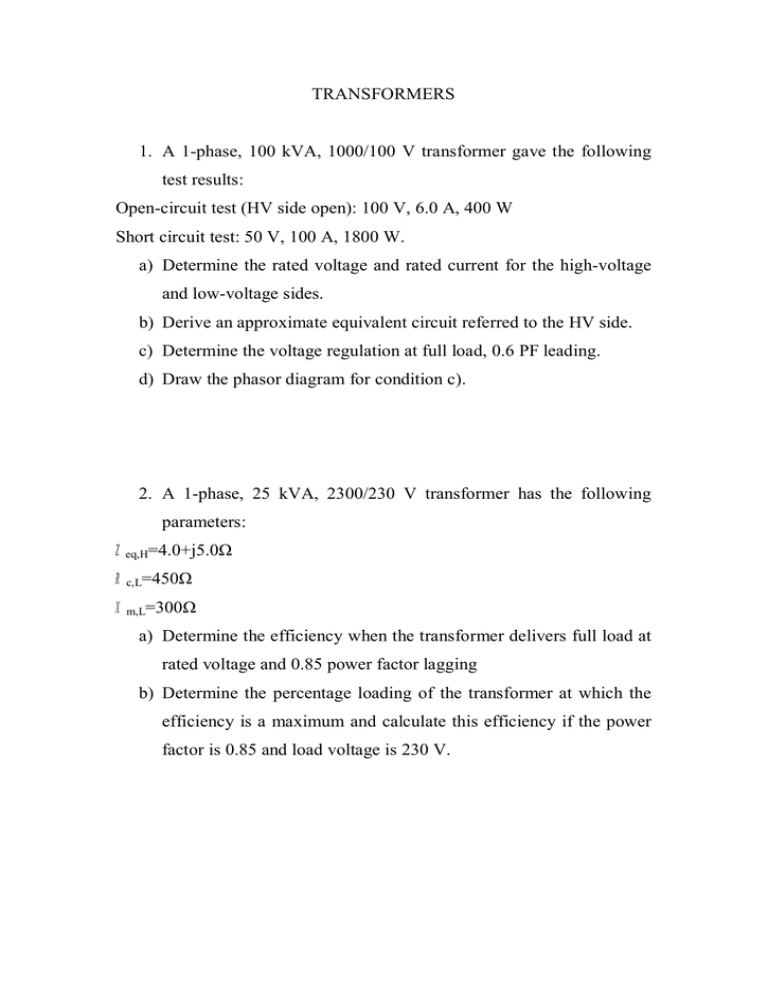
TRANSFORMERS 1. A 1-phase, 100 kVA, 1000/100 V transformer gave the following test results: Open-circuit test (HV side open): 100 V, 6.0 A, 400 W Short circuit test: 50 V, 100 A, 1800 W. a) Determine the rated voltage and rated current for the high-voltage and low-voltage sides. b) Derive an approximate equivalent circuit referred to the HV side. c) Determine the voltage regulation at full load, 0.6 PF leading. d) Draw the phasor diagram for condition c). 2. A 1-phase, 25 kVA, 2300/230 V transformer has the following parameters: Zeq,H=4.0+j5.0 Rc,L=450 Xm,L=300 a) Determine the efficiency when the transformer delivers full load at rated voltage and 0.85 power factor lagging b) Determine the percentage loading of the transformer at which the efficiency is a maximum and calculate this efficiency if the power factor is 0.85 and load voltage is 230 V. 3. Three one-phase, 10 kVA, 460/120 V, 60 Hz transformers are connected to form a 3 phase, 460/208 V transformer bank. The equivalent impedance of each transformer referred to the highvoltage side is 1.0+j2.0 . The transformer delivers 20 kW at 0.8 power factor (leading). a) Draw a schematic diagram showing the transformer connection, b) Determine the transformer winding current, c) Determine the primary voltage, d) Determine the voltage regulation. 4. Three identical single-phase transformers, each of rating 20 kVA, 2300/230 V, 60 Hz, are connected Y-Y to form a three-phase transformer bank. The high-voltage side is connected to a threephase, 4000 V, 60 Hz supply, and the secondary is left open. The neutral of the primary is not connected to the neutral of the supply. The voltage between the primary neutral and the supply neutral is measured to be 1200 V. a) Describe the voltage waveform between primary neutral and supply neutral. Neglect harmonics higher than third. b) Determine the ratio of (i) phase voltages of the two sides and (ii) line voltages of the two sides. c) Determine the ratio of the rms line–to-line voltage to the rms lineto-neutral voltage on each side.
