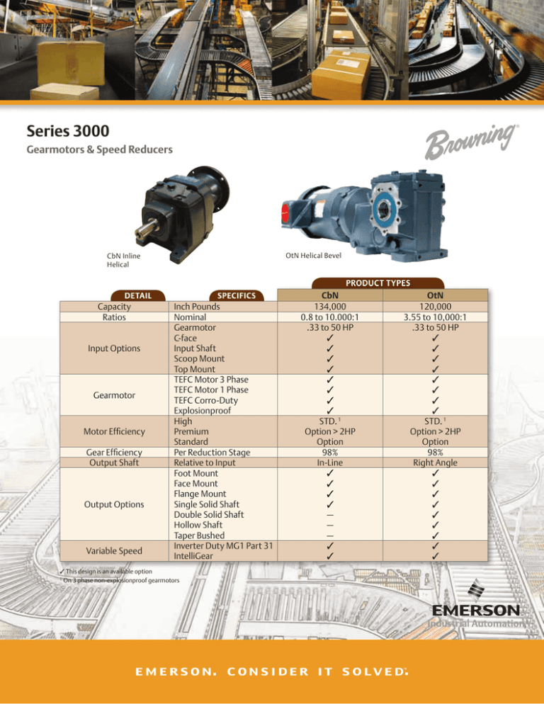
Series 3000
Gearmotors & Speed Reducers
OtN Helical Bevel
CbN Inline
Helical
PRODUCT TYPES
DETAIL
Capacity
Ratios
Input Options
Gearmotor
Motor Efficiency
Gear Efficiency
Output Shaft
Output Options
Variable Speed
SPECIFICS
Inch Pounds
Nominal
Gearmotor
C-face
Input Shaft
Scoop Mount
Top Mount
TEFC Motor 3 Phase
TEFC Motor 1 Phase
TEFC Corro-Duty
Explosionproof
High
Premium
Standard
Per Reduction Stage
Relative to Input
Foot Mount
Face Mount
Flange Mount
Single Solid Shaft
Double Solid Shaft
Hollow Shaft
Taper Bushed
Inverter Duty MG1 Part 31
IntelliGear
This design is an available option
1
On 3 phase non-explosionproof gearmotors
CbN
134,000
0.8 to 10.000:1
.33 to 50 HP
STD. 1
Option > 2HP
Option
98%
In-Line
—
—
—
OtN
120,000
3.55 to 10,000:1
.33 to 50 HP
STD. 1
Option > 2HP
Option
98%
Right Angle
Choose Browning® Series 3000 Gearmotors & Speed Reducers
EMERSON ® HE GEARMOTORS LEAD EFFICIENCIES IN NORTH AMERICA
Reference
Full Load Nom. Efficiency % / HP @ 1750 RPM
1/3
1/2
3/4
1
1.5
2
3
5
7.5
10
15
20
25
30
40
50
Emerson 6/10
75
80
80
84
84
85.5
89.5
89.5
91
91
92.4
93
93
93.6
94.1
94.5
*Canada 1/11
n/a
n/a
n/a
82.5
84
84
87.5
87.5
89.5
89.5
91
91
92.4
92.4
93.0
93.0
*USA 12/10
n/a
n/a
n/a
82.5
84
84
87.5
87.5
89.5
89.5
91
91
92.4
92.4
93.0
93.0
* C-face Ftls. Motor Requirements and date effective
Exceeds industry High Efficiency specifications
FEATURES
BENEFITS
1
3 Phase HE Gearmotors use High
Efficiency motors starting @ .33hp
• Meets or exceeds Efficiency Standards in North America for
gearmotors and C-face motors
• Delivers maximum power savings coupled with high
efficiency gearing
2
Gearmotors utilize a “modular”
connection between gear and motor
• Allows motor replacements on site without draining oil,
disturbing gear-to-load connections or having to remove
primary pinion
• Users can upgrade to High Efficiency motor from original
older lower efficiency designs
• Only one spare motor required per HP/Voltage/Phase
regardless of the gear styles present in a factory
3
Synthetic hydrocarbon lubricant is
supplied standard from factory
• Allows a wider ambient range with stable optimum viscosity
• Coupled with special breather supplied, maintenance is just
checking to ensure correct oil volume without seasonal oil
changing cycles
4
SMTP design taper bushed system with
stabilizer ring is a standard option for OtN
gearing for shaft mount applications
• Output shaft machining allows mounting of bushing onto
either side of output shaft for maximum mounting flexibility
• Static bushing locking angle and use of stabilizer ring helps
to eliminate fretting making future removal quick and easy
5
Non-hazardous 3 phase motor
constructed with minimum Class F
winding materials selected to meet NEMA
MG1 Part 31 standards. Motor designs
run at lower than Class B temperature
rises at full load
• Cooler operating temperatures of motors with Class F
materials translates to thermal capability for 100,000 hours
winding life
• Most gearmotors can deliver 5:1 full constant torque with
proper PWM controller tuning and within standard warranty
6
IntelliGear variable speed gearmotor
available from 1/3 to 10 HP for 115V,
230V and 460V power supplies
• Packages gearmotor with open loop vector controller,
pre-programmed and tested for up to 30:1 constant torque
speed ranges at 100% load
• Standard combination is TEFC motor plus IP65 controller for
use indoors or outdoors
INTELLIGEAR ®
VARIABLE
SPEED
GEAMOTOR
Power Supply
Motor
HP
115V
230V
460V
.33 to .75
1 to 5
–
7.5 to 10
–
–
Highly Modular
• Modular, tapered connection so
that one spare of each motor
hp size in the plant will allow
replacement of that hp
on any frame size of the
gearmotor – so users can
keep fewer spares in stock
• Taper connection makes
motor replacement easy,
eliminating the need for draining
the oil or breaking open the
gearcase
Competitor gearmotor designs
have the primary pinion
located on the motor shaft.
Innovative, self-locking, tapered shaft
connection between motor and shaft
APPLICATION CONSIDERATIONS
The proper selection and application of power transmission products and components, including the related area of product safety, is the responsibility of the customer. Operating and performance requirements
and potential associated issues will vary appreciably depending upon the use and application of such products and components. The scope of the technical and application information included in this publication
is necessarily limited. Unusual operating environments and conditions, lubrication requirements, loading supports, and other factors can materially affect the application and operating results of the products and
components and the customer should carefully review its requirements. Any technical advice or review furnished by Emerson Power Transmission Corporation and its divisions with respect to the use of products and
components is given in good faith and without charge, and Emerson assumes no obligation or liability for the advice given, or results obtained, all such advice and review being given and accepted at customer’s risk.
Customer Service
1 800 626 2120
www.emerson-ept.com
For a copy of our Standard Terms and Conditions of Sale, Disclaimers of Warranty, Limitation of Liability and Remedy, please contact Customer Service at 1-800-6262120. These terms and conditions of sale, disclaimers and limitations of liability apply to any person who may buy, acquire or use an Emerson Power Transmission
Corporation product referred to herein, including any person who buys from a licensed distributor of these branded products.
Emerson Power Transmission does not warrant the accuracy of the information contained in this document. All interchanges should be compared with actual current
specifications and/or manufacturing drawings. For a copy of our standard terms and conditions, contact Emerson Power Transmission at 1-800-626-2120.
Browning, Emerson, Emerson. Consider It Solved., Emerson Industrial Automation and Intelligear are trademarks
of Emerson Electric Co. or one of its affiliated companies.
©2013 Emerson Power Transmission Corp., All Rights Reserved. MCF13006E • Form 9346E • Printed in USA


