Designing with Thermally Protected TCMOV Varistors for Type 1 and
advertisement
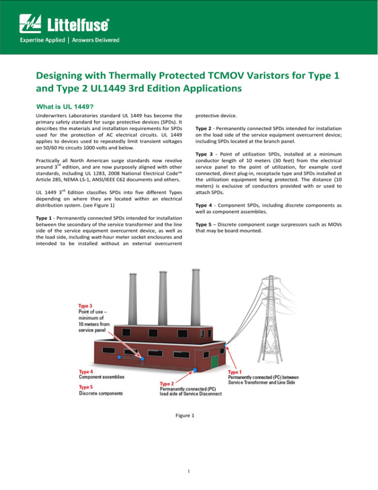
Designing with Thermally Protected TCMOV Varistors for Type 1 and Type 2 UL1449 3rd Edition Applications What is UL 1449? protective device. Type 2 ‐ Permanently connected SPDs intended for installation on the load side of the service equipment overcurrent device; including SPDs located at the branch panel. Type 3 ‐ Point of utilization SPDs, installed at a minimum conductor length of 10 meters (30 feet) from the electrical service panel to the point of utilization, for example cord connected, direct plug‐in, receptacle type and SPDs installed at the utilization equipment being protected. The distance (10 meters) is exclusive of conductors provided with or used to attach SPDs. Type 4 ‐ Component SPDs, including discrete components as well as component assemblies. Type 5 – Discrete component surge surpressors such as MOVs that may be board mounted. Underwriters Laboratories standard UL 1449 has become the primary safety standard for surge protective devices (SPDs). It describes the materials and installation requirements for SPDs used for the protection of AC electrical circuits. UL 1449 applies to devices used to repeatedly limit transient voltages on 50/60 Hz circuits 1000 volts and below. Practically all North American surge standards now revolve rd around 3 edition, and are now purposely aligned with other standards, including UL 1283, 2008 National Electrical Code™ Article 285, NEMA LS‐1, ANSI/IEEE C62 documents and others. UL 1449 3rd Edition classifies SPDs into five different Types depending on where they are located within an electrical distribution system. (see Figure 1) Type 1 ‐ Permanently connected SPDs intended for installation between the secondary of the service transformer and the line side of the service equipment overcurrent device, as well as the load side, including watt‐hour meter socket enclosures and intended to be installed without an external overcurrent Figure 1 1 Designing with Thermally Protected TCMOV Varistors for Type 1 and Type 2 UL1449 3rd Edition Applications The device is subjected to 15 impulses at the specified discharge current, with MCOV applied between impulses; to pass the test the unit must be fully functional and the pre‐ and post‐VPR clamping levels cannot vary by more than ±10%. It is important to note that the test now includes any current limiting devices (internal or external); the overcurrent limiting device must be in the current path and be subjected to the same impulse as the SPD. This test is considerably more stringent than the earlier test, because it causes heat to accumulate in the SPD and associated devices. During the test, the SPD cannot have any opens in the surge path nor create any fire or shock hazard. UL 96A Lightning Protection Master Label impact: In the past, UL 96A required that surge suppressors be evaluated as secondary arrestors. There were issues associated with different regulation and administration. Secondary arrestors now evolve into Type 1 SPDs, and UL 96A will accept Type 1 or Type 2 SPDs having 20kA nominal ratings. First time approval as American National Standard (ANSI): The third edition of UL 1449 is now an ANSI standard, and its official designation is ANSI/UL 1449 – 2006. As an ANSI standard it is subject to review and voting by a technical review panel, but as far as manufacturers and other users of SPDs are concerned it has little effect. Designing to Comply with UL 1449 3rd Edition Introduction: Metal Oxide Varistors (MOVs) are commonly used to suppress transients in many applications such as: Surge Protection Devices (SPD), Uninterruptible Power Supplies (UPS), AC Power Taps, AC Power Meters or other products. Lightning, inductive load switching, or capacitor bank switching, are often the sources of these over‐voltage transients. Under normal operating conditions, the AC line voltage applied to an MOV is not expected to exceed the MOV’s Maximum ACRMS Voltage Rating or Maximum Continuous Operating Voltage (MCOV). Occasionally, over‐voltage transients may occur that exceeds these limits. These transients are clamped to a suitable voltage level by the MOV provided the transient energy does not exceed the MOV’s maximum rating. Table 1 Abnormal Overvoltage, Limited and Intermediate Current Requirements: In AC line applications, the loss of a Neutral‐Ground connection may occur in such a way that there exists a risk that a sustained over‐voltage may be applied to an MOV that is rated for a much lower continuous voltage. In an unlimited current condition the MOV will first fail to a low impedance (few Ohms), but due to the high amount of energy available, it most often ruptures instantaneously. If, however, there are loads tied to the AC line that limit current flow, the MOV can overheat and potentially cause the SPD device to overheat resulting in smoke, out‐gassing and eventually fire. Surge Testing: Type 1 devices are to be tested at 10kA or 20kA, while Type 2 devices can be tested at 3, 5, 10, or 20kA. (See Table 1) The SPD manufacturer selects the type and the surge level for the product before testing. The SPD manufacturer also selects the MCOV (Maximum Continuous Operating Voltage) per mode to apply to the unit under test. Once those two parameters have been established by the SPD manufacturer, the test can start. 2 Designing with Thermally Protected TCMOV Varistors for Type 1 and Type 2 UL1449 3rd Edition Applications For example, in a standard U.S. 120V AC Line application, two 120V AC power lines (180° out of phase) are commonly fed from a center‐tapped 240V transformer. See Figure 2. Let’s assume a 150V rated MOV is present in the top 120V circuit, and some load exists on the bottom 120V circuit. Both the MOV and load share the center tap which is the Neutral‐ Ground Connection. If a break occurs on the center tap (X—X), then the load in the bottom phase acts as a current limiter and the line fuse may not clear. In this scenario, the 150V rated MOV is subjected to 240V at a limited current potentially resulting in thermal run away for the MOV. Table 39‐1 in UL1449 3rd Edition defines the test voltage that should be applied to various SPD devices depending on the designer’s desired device rating. (See Table 2) MOVs can also be subjected to continuous abnormal voltage conditions rather than short duration transients. If an MOV is subjected to a sustained abnormal over‐voltage, limited current condition (as is required in UL1449), the MOV may go into thermal runaway resulting in overheating, smoke, and potentially fire. For end products to comply with UL1449, some level of protection must be afforded to the MOV to prevent this failure mode. UL1449 also requires an intermediate current abnormal overvoltage test. Here, the SPD is subjected to a series of abnormal voltage events of a level insufficient to cause full breakover but sufficient to cause the device to conduct a substantial current, which it must withstand over a specified number of cycles without being damaged or destroyed. (See.Table.3) Figure 2 Table 3 Table 2 3 Designing with Thermally Protected TCMOV Varistors for Type 1 and Type 2 UL1449 3rd Edition Applications Using TCMOV for Type 1 and Type 2 Applications: A new technology has been developed that will aid the designer in meeting UL1449 requirements including the sustained abnormal over‐voltage limited current testing, while eliminating most of the problems associated with other methods. This technology is a fully integrated, thermally self‐ protected MOV ‐ TMOV Varistor Series. This new device uses a patent pending thermal element internal to the MOV so that it is in direct contact with the metal oxide disk, allowing for optimum heat transfer. Because of the proximity of the thermal element to the MOV body, a higher opening temperature element can be used. This allows the thermally self‐protected MOV to be wave soldered simplifying the assembly process. The construction method also allows the new device to perform to standard MOV ratings with regards to peak current, peak energy, voltage clamp levels, etc. while providing the safety of a thermally protected device. Figure 3 illustrates the integrated function. y y y The device integrates a micro‐switch which is triggered by a mechanical structure that makes the indicator circuit isolated from the main power. Recognized by UL1449 the 3rd edition under UL File number E320116. Lead‐free and RoHS compliant A simple block diagram of a typical line voltage transient protection scheme used to meet the sustained abnormal over‐ voltage, limited current test requirements of UL1449 is shown in Figure 4. A TCMOV34 or several TCMOVs in parallel are each placed across each of the three conductive pairs; L‐N, L‐G, and N‐G. This offers the utmost protection for any possible line transient. A standard fuse is placed in series with the line to protect the system from an over current condition that exceeds a predetermined level. Typically, the.current rating of this fuse is higher than the limited current flowing through the circuit during UL1449 testing and the fuse must be able to withstand Inom surge testing without opening. Figure 3 TCMOV helps facilitate SPD module compliance to UL1449 for Type 1 and Type 2 SPD applications. The device integrates a micro‐switch which is triggered by a mechanical structure that makes the indicator circuit isolated from the main power. The Figure 4 TCMOV devices offer quick thermal response due to the close proximity of the integrated thermal element to central part of the MOV body. This ensures a safe and quick disconnect during the highest Abnormal Overvoltage Intermediate Current tests in UL1449 3rd Edition. Once the thermal element of a thermally protected varistor opens, it is important that the element stay open and that a reconnection not occur. The TCMOV device will also pass 20kA Inom testing requirements and is capable of 200kA SCCR (Short Circuit Current Rating). TCMOV34 Specifications: y y Short circuit current rating: 200kA, In value: 20kA TCMOV consists of a 40kA varistor with an integral thermal disconnect system designed to open in the event of overheating due to abnormal over‐voltage conditions. 4 Designing with Thermally Protected TCMOV Varistors for Type 1 and Type 2 UL1449 3rd Edition Applications The Littelfuse Varistor Surge Protection (LVSP) Fuses are intended for the protection of SPD products. The LVSP Series has been designed to survive the 8x20μs lightning surges described in various Standards (UL1449, IEC61000‐4‐5 & IEEE C62.41) without opening. Surge fusing: Littelfuse also offers the LVSP family of surge fuses that will help SPD manufacturers meet UL1449 requirements. Complementary Littelfuse products for SPD applications: performance and minimize energy let‐through into the system. These SADs that are placed downstream of the main SPD and will need to be coordinated together. Littelfuse offers a full range of Gas Discharge Tubes (GDT) and Silicon Avalanche Diodes (SAD) to complement varistor solutions. SADs in particular can help improve overall clamping References: 3. Littelfuse Application Note – EC635 Designing with Thermally Protected TMOV® Varistors in SPD and AC Line Applications, May 2011. rd 1. Surge Protective Devices ‐ UL1449 3 Edition, April 19, 2010. 2. Littelfuse Datasheet, TCMOV34, Feb 2012. 5 Designing with Thermally Protected TCMOV Varistors for Type 1 and Type 2 UL1449 3rd Edition Applications FAQ: Q. What is the Switch Specification? A. It is available from our datasheet Q. Can TCMOV pass the dielectric test? P1‐S1 P2‐S2? A. Yes, TCMOV passed the dielectric test of 2500Vac‐4500Vac. Q. Is a short/trimmed lead version available? A. We could do it based on customer’s request. Q. Concerns on the lead spacing (S2 ‐ P2): Clearance Distance and Creepage Distance (Pollution Degree 3 PCB). A. According to UL840, 1, Clearance distance, minimum 5.5mm for Type 1 SPD at 600V and Pollution degree 3. Confirmed TCMOV has 5.7mm between P2 and S2, we are ok to meet the requirement presently. 2, Creepage distance, minimum 10.0mm for pollution degree 3 at 600V: actually our P2 did not touch the housing case; therefore, the voltage will not be able to creep from P2 to S2. Besides, the minimum acceptable Creepage distance on printed board (PCB) is 3.2mm, see attached UL840, page 13.Therefore, we should be fine as well. Q. Any potential issues with shelf life? A. TCMOV has pasted 85°C, 1000 hours test. Therefore, there is no shelf life test at good storage condition. But, we normally would recommend two years shelf life. Need MTBF report! Q. SSCR Test at what voltage and where these parts are tested at? A. The test coupled Vac is based on the Table 39.1 from UL. Q. Confirmation of the Nominal Discharge Current, In = 20,000A, for the >= 300VRMS parts. A. The In of TCMOV34S321MP is 20kA. Q. Can LF offer 690V rating in the TCMOV series? A. We can offer 690V part, but it needs 7~9 months, because we have to make one new case mold and conduct overall testing and get UL approval. Q. Can LF offer the TCMOV with no Switch? A. the Non‐Switch version will be available by May11. 6
