Document
advertisement

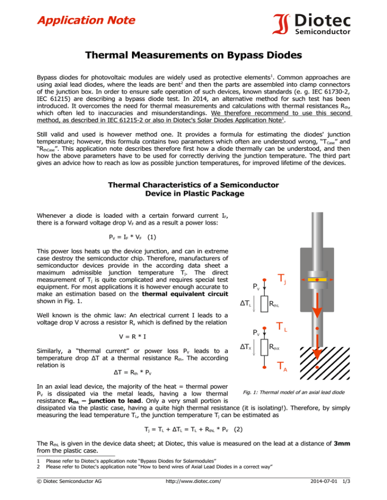
Application Note Thermal Measurements on Bypass Diodes Thermal Measurements on Bypass Diodes Bypass diodes for photovoltaic modules are widely used as protective elements 1. Common approaches are using axial lead diodes, where the leads are bent2 and then the parts are assembled into clamp connectors of the junction box. In order to ensure safe operation of such devices, known standards (e. g. IEC 61730-2, IEC 61215) are describing a bypass diode test. In 2014, an alternative method for such test has been introduced. It overcomes the need for thermal measurements and calculations with thermal resistances R th, which often led to inaccuracies and misunderstandings. We therefore recommend to use this second method, as described in IEC 61215-2 or also in Diotec's Solar Diodes Application Note1. Still valid and used is however method one. It provides a formula for estimating the diodes' junction temperature; however, this formula contains two parameters which often are understood wrong, “T Case” and “RthCase”. This application note describes therefore first how a diode thermally can be understood, and then how the above parameters have to be used for correctly deriving the junction temperature. The third part gives an advice how to reach as low as possible junction temperatures, for improved lifetime of the devices. Thermal Characteristics of a Semiconductor Device in Plastic Package Whenever a diode is loaded with a certain forward current IF, there is a forward voltage drop VF and as a result a power loss: PV = IF * VF (1) This power loss heats up the device junction, and can in extreme case destroy the semiconductor chip. Therefore, manufacturers of semiconductor devices provide in the according data sheet a maximum admissible junction temperature Tj. The direct measurement of Tj is quite complicated and requires special test equipment. For most applications it is however enough accurate to make an estimation based on the thermal equivalent circuit shown in Fig. 1. Tj PV ΔTL RthL Well known is the ohmic law: An electrical current I leads to a voltage drop V across a resistor R, which is defined by the relation TL PV V=R*I Similarly, a “thermal current” or power loss PV leads to a temperature drop ΔT at a thermal resistance Rth. The according relation is ΔT = Rth * PV ΔTX RthX TA In an axial lead device, the majority of the heat = thermal power Fig. 1: Thermal model of an axial lead diode PV is dissipated via the metal leads, having a low thermal resistance RthL – junction to lead. Only a very small portion is dissipated via the plastic case, having a quite high thermal resistance (it is isolating!). Therefore, by simply measuring the lead temperature TL, the junction temperature Tj can be estimated as Tj = TL + ΔTL = TL + RthL * PV (2) The RthL is given in the device data sheet; at Diotec, this value is measured on the lead at a distance of 3mm from the plastic case. 1 2 Please refer to Diotec's application note “Bypass Diodes for Solarmodules” Please refer to Diotec's application note “How to bend wires of Axial Lead Diodes in a correct way” © Diotec Semiconductor AG http://www.diotec.com/ 2014-07-01 1/3 Thermal Measurements on Bypass Diodes The device shown in figure 1 is connected to an infinite heatsink having the temperature T A (A = Ambient). The thermal resistance RthX contains all the thermal path from the diodes' leads via the clamp connectors and the cables to the ambient air, which is assumed to be constant. It is normally unknown; when TL is known, RthX can be derived however by the formula RthX = ΔTX / PV = (TL – TA) / PV In the data sheet of Diotec and also of competitors there is another parameter given, the thermal resistance junction to ambient or RthA. This value is indeed measured when the leads are connected in 10mm distance from the case to again an infinite heatsink; it is of mainly theoretical interest however. At a real diode, of course both leads are connected to a any kind of “heatsink”, the values given in the data sheets are considering this fact. In the before mentioned standards, the module short circuit current ISC is applied for one hour to the diode, at an ambient temperature of 75°C. During the test, the junction temperature of the device has to stay below the maximum admissible value. Following above formulas (1) and (2), the standards provide this estimation for junction temperature: Tj = TCase + RthCase * VF * ISC It should be clear that VF is the measured forward voltage drop across the diode after it has reached a thermal equilibrium. ISC is the short circuit current of the photovoltaic module, applied to the diode. More critical however are the terms “TCase” and “RthCase”, which are defined in the following. Correct Definition and Usage of TCase and RthCase testpoint for TCase Former diode packages were fully made of metal, such as the DO-4 package shown in Fig. 2. Therefore, the reference point for the parameter RthC = “thermal resistance junction to case” was set on the edge of the metallic device package or “case”. testpoint Tcase = TL! As described earlier, at axial lead diodes the relevant thermal resistance is the one of the leads – RthL, see Fig. 3. The plastic case has got a quite high Rth, which is not useful at all. Fig. 2: Diode in full metal case 1 Therefore, at axial lead packages, the temperature of the leads TL (in the specified distance from case – 3mm at Diotec) has to be used rather than “TCase”. Instead of the non-defined “RthCase”, the value RthL specified in the data sheet has to be used1! 3 Fig. 3: Axial lead diode with plastic case Some competitors are specifying a value RthCase; its value is however impossible low for a plastic case and therefore more likely the value RthL 2/3 2014-07-01 http://www.diotec.com/ © Diotec Semiconductor AG Application Note Thermal Measurements on Bypass Diodes How to Reduce Thermal Resistance From Fig. 1 it is obvious that the junction temperature can be reduced by reducing the values of R thL and RthX. The “X” series of axial lead diodes by Diotec offers drastically reduced values RthL. At the same semiconductor die size, the innovative “X” package outline reduces RthL from 4 K/W down to 2.1 K/W, see Fig. 4 (L = 3mm). Further devices in this package are e. g. the FX2000A or SBX2540 1. The value RthX is normally the bigger value and as such has got the bigger influence on Tj. The thermal resistance of a lead wire increases almost linearly with its length, see Fig. 4. As a consequence, the length of the leads “L” from device case to the clamp connectors has to be as short as possible, see Fig. 5. 24 [K/W] 20 16 L SB1240 12 8 SBX2040 4 Fig. 5: L has to be as short as possible! RthL 0 0 L 4 8 12 [mm] Typ. thermal resistance vs lead length Typ. therm. Widerst. in Abh. der Anschlusslänge Fig. 4: At the same die size, the “X” package has superior thermal performance 2 There are further parts of RthX formed by the clamps, the cables and so on. The bigger the cross section of those parts, the lower is their thermal resistance and in consequence RthX and Tj! Newer designs of junction boxes use a PCB or a copper lead frame where diodes in power packages, such as TO-220 or D²PAK, are assembled on. The advantage of these package outlines is their tab or flange that allows for direct and tight heat sink connection. Thus the heat can be dissipated much more easy from the semiconductor junction to the case outline. The reference point for “TCase” = TC and “RthCase” = RthC is shown in Fig. 6. It is again the metal part of the flange and not the plastic case. Typical part names by Diotec in TO-220 are the FT2000 or SBT18 series, as well as the KT20A120 – Protectifiers® 2. In D²PAK there are the SK2040YD2 or FR20DAD2. There are also versions of the TO-220 with isolated flange, such as the SBJ1845. Only here the TC and RthC are specified on the plastic “case” respectively tab at the same position as shown in Fig 6. 1 2 testpoint Tcase = TC! Type Typ Fig. 6: Power package outline Data sheets see www.diotec.com Protectifiers® by Diotec are devices with special reverse overvoltage protection against lightning, ESD etc. Data sheets see www.diotec.com © Diotec Semiconductor AG http://www.diotec.com/ 2014-07-01 3/3


