Site preparation ® 622sd Daylight Emulation® Luminaire Page 1
advertisement
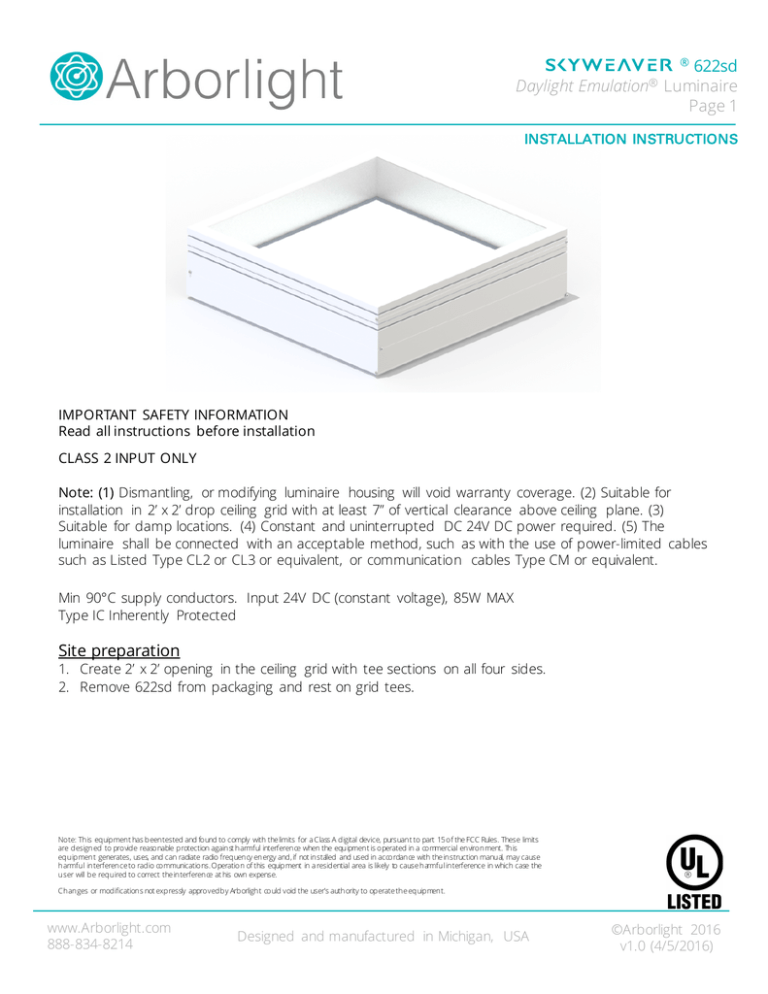
622sd Luminaire Page 1 ® Daylight Emulation® INSTALLATION INSTRUCTIONS IMPORTANT SAFETY INFORMATION Read all instructions before installation CLASS 2 INPUT ONLY Note: (1) Dismantling, or modifying luminaire housing will void warranty coverage. (2) Suitable for installation in 2’ x 2’ drop ceiling grid with at least 7” of vertical clearance above ceiling plane. (3) Suitable for damp locations. (4) Constant and uninterrupted DC 24V DC power required. (5) The luminaire shall be connected with an acceptable method, such as with the use of power-limited cables such as Listed Type CL2 or CL3 or equivalent, or communication cables Type CM or equivalent. Min 90°C supply conductors. Input 24V DC (constant voltage), 85W MAX Type IC Inherently Protected Site preparation 1. Create 2’ x 2’ opening in the ceiling grid with tee sections on all four sides. 2. Remove 622sd from packaging and rest on grid tees. Note: This equipment has been tested and found to comply with the limits for a Class A digital device, pursuant to part 15 of the FCC Rules. These limits are designed to provide reasonable protection against harmful interference when the equipment is operated in a commercial environment. This equipment generates, uses, and can radiate radio frequency energy and, if not installed and used in accordance with the instruction manual, may cause harmful interference to radio communications. Operation of this equipment in a residential area is likely to cause harmful interference in which case the user will be required to correct the interference at his own expense. Changes or modifications not expressly approved by Arborlight could void the user's authority to operate the equipment. www.Arborlight.com 888-834-8214 Designed and manufactured in Michigan, USA ©Arborlight 2016 v1.0 (4/5/2016) 622sd Luminaire Page 2 ® Daylight Emulation® 622sd INSTALLATION STEP 1 Using wiring legend, connect Class 2 24V DC power using to external connectors. Wires from the 24VDC power supply (A) should enter the female connector; there are multiple wire terminals for pass through wiring to connect to adjacent fixtures. Wires from the Luminaire (B) enter the male connector. 1 A Wiring Legend Line 24VDC+ B 24VDC Return Load RED BLACK 2 E G C STEP 2 Consult Skyweaver ® Luminaire Communications Hub SW6H installation manual to determine low voltage wiring requirements. F D www.Arborlight.com 888-834-8214 If using wired connections between the hub and fixture, use wire from the Hub + Signal (C) to Red fixture + Signal Input (D) wire and Hub – Signal (E) to the Black fixture – Signal Input (F) wire. If connecting multiple fixtures, connect corresponding wires (G) into the fixture side of the connectors. Designed and manufactured in Michigan, USA ©Arborlight 2016 v1.0 (4/5/2016) 622sd Luminaire Page 3 ® Daylight Emulation® STEP 3 Lift and rotate rotate panel upwards (H) towards track until fully seated (I) 3 Note To remove glazing panel for wiring compartment access, release the two latches using a card or other thin implement (J) STEP 4 Energize circuit. The luminaire will immediately illuminate to a dim level, indicating a successful installation and will remain in this state until commissioned with the Skyweaver ® Luminaire Communications Hub SW6H. H 4 I J www.Arborlight.com 888-834-8214 Designed and manufactured in Michigan, USA ©Arborlight 2016 v1.0 (4/5/2016)
