General-Use Potentiometer Tuning
advertisement

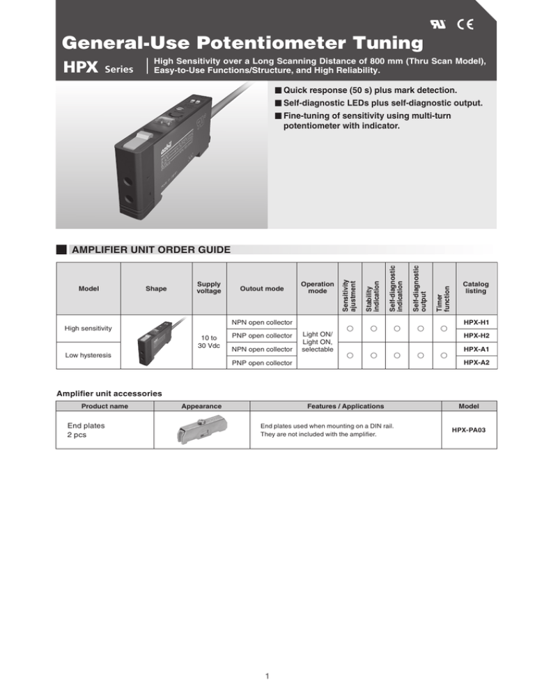
General-Use Potentiometer Tuning HPX Series High Sensitivity over a Long Scanning Distance of 800 mm (Thru Scan Model), Easy-to-Use Functions/Structure, and High Reliability. Quick response (50 s) plus mark detection. Self-diagnostic LEDs plus self-diagnostic output. Fine-tuning of sensitivity using multi-turn potentiometer with indicator. Operation mode NPN open collector High sensitivity 10 to 30 Vdc Low hysteresis PNP open collector NPN open collector PNP open collector Light ON/ Light ON, selectable Timer function Outout mode Self-diagnostic output Supply voltage Self-diagnostic indication Shape Stability indication Model Sensitivity ajustment AMPLIFIER UNIT ORDER GUIDE Catalog listing HPX-H1 HPX-H2 HPX-A1 HPX-A2 Amplifier unit accessories Product name End plates 2 pcs Appearance Features / Applications End plates used when mounting on a DIN rail. They are not included with the amplifier. 1 Model HPX-PA03 AMPLIFIER UNIT SPECIFICATIONS Specifications High sensitivity HPX-H1 Low hysteresis HPX-A1 HPX-H2 HPX-A2 Light emitter Red four-element LED Power 12–30 Vdc (ripple: 10% max.) Output type PNP open collector NPN open collector Current consumption Control 35 mA max. Output : 100 mA max. (resistive load) Switching current output Self-diagnosis output : 50 mA max. Residual voltage 1V max. (at 100 mA load current) Output withstand voltage 30V max. Span adjustment (sesitivity adjustment) 3-turn variable resistor Response time 500 μs max. (Without off-delay) Indicator Red ‘ON’ with reception of light, Green ‘ON’ with stable or stablr dark. Green ‘BLINK’ with self diagnosis. Ambient light immunity Incandescent light: 5,000 lux max. Sunlight: 20,000 lux max. Operating temperature –20 to + 60°C (–20 to +50°C when setting tightly side by side) Operating humidity 35–85% RH (without condensation) Vibration resistance 10–55 Hz, 1.5 mm peak-to-peak amplitude, 2 hours each in X, Y and Z directions Shock resistance 500 m/s 2, 3 times each in X, Y and Z directions Protection circuits Short-circuit protection circuit for power, malfunction prevention circuit at power ON (approx. 100 ms). power reverse connection protection circuit Case material PC/ABS alloy Weight Approx. 55 g DETAILED VIEW OF THE OPERATING PANEL Sensitivity adjustor (3turns) Light indicator (red) L-ON/D-ON selector Off-delay switch Stability indicator (green) Indicator 2 EXTERNAL DIMENSIONS (unit: mm) Amplifier unit HPX-H, A, F (in common) When mounted on bracket (attached) When mounted on DIN rail 3 OUTPUT CIRCUIT DIAGRAM NPN output type PNP output type OUTPUT AND INDICATOR OPERATION CHART In both dark-ON (D-ON) and light-ON (L-ON) modes, if the switch is operating with insufficient light (for example, if the amount of light has decreased due to accumulation of dirt), the user is notified by latched self-diagnosis output and indicator. Amt. of light received Stable light level (1.5 × operation level) Detection level (operation level) Stable blocked light level (0.8 × operation level) Time Lit Light level indicator (red) Control output Lit Lit Lit Blinking Lit Control output Stability indicator (green) & self-diagnosis indicator Lit Lit Lit Lit Selfdiagnosis Self-diagnosis output There is no problem. The amount of light is sufficient. The amount of light is low. If this state persists, notification is given by self-diagnosis output and by indicator. Explanation of the chart 1. After the photoelectric switch operates at a light level that is below the stable light level (point in the above figure), when it reaches the stable blocked light level (point ), the stability indicator starts blinking (self-diagnosis indication). At the same time, the self-diagnosis output turns ON and latches. 2. Afterward, when the amount of light received by the photoelectric switch reaches the stable light level (point ), the stability indicator (self-diagnosis indication) stops blinking. At the same time, the self-diagnosis output turns OFF and is unlatched. 4 SENSITIVITY ADJUSTMENT POTENTIOMETER For retroreflective switches Adjustment method Green Red Lit Unlit Green Red Lit Lit With no target object present, turn the potentiometer counterclockwise from the MAX position and stop at the position where the indicators appear as shown on the left. This is position . If the red indicator is unlit even when the potentiometer is at the maximum position, MAX is position . Place a target object in the appropriate position, turn the potentiometer clockwise from the MIN position, and stop at the position where the indicators appear as shown on the left. This is position . Green Red Lit Lit Lit Unlit (Stable light) Set the potentiometer to the midpoint between and . (Stable blocked light) Note: If the potentiometer rotates one revolution or more, adjust it based on the indicator position. For thru-scan switches 1) When detecting translucent target objects Adjustment method Green Red Lit Unlit Green Red Lit Lit Place a target object in the appropriate position, turn the potentiometer counterclockwise from the MAX position, and stop at the position where the indicators appear as shown on the left. This is position . If the red indicator is unlit even when the potentiometer is at the maximum position, MAX is position . With no target object present, turn the potentiometer clockwise Green from the MIN position and stop at the position where the indica- Red (Stable light) Lit tors appear as shown on the left. This is position . Lit Set the potentiometer to the midpoint between and . Lit Unlit (Stable light shielding) Note: If the potentiometer rotates one revolution or more, adjust it based on the indicator position. 2) When detecting opaque target objects In the following two cases, adjust the optical axis and sensitivity so that the indicators appear as shown. Green Red Lit Unlit Green Red Lit Lit (Stable blocked light) (Stable light) 5 BASIC PRECAUTIONS switch switch switch’s Before use, thoroughly read the “Precautions for use” and “Precautions for handling” in the Technical Guide on pages A-141 to A-156 as well as the instruction manual and product specification for this switch. 6


