LIEBERT® INTELLISLOT™ RELAY CARD
Product Specification/Installation Sheet
Description
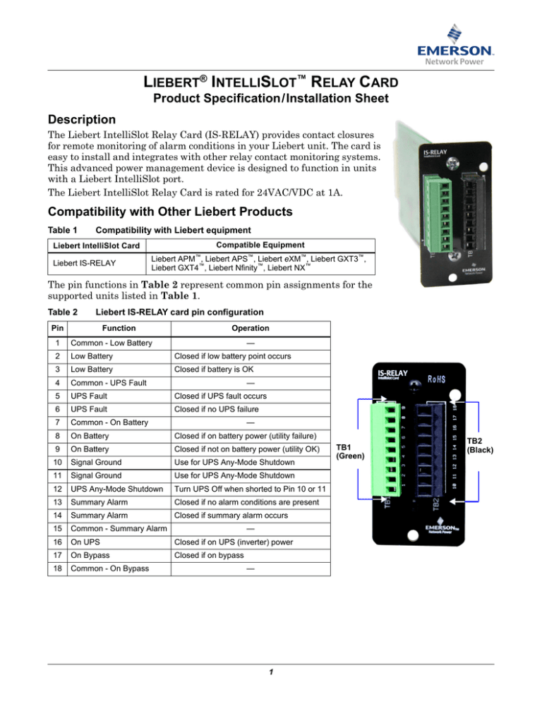
The Liebert IntelliSlot Relay Card (IS-RELAY) provides contact closures
for remote monitoring of alarm conditions in your Liebert unit. The card is
easy to install and integrates with other relay contact monitoring systems.
This advanced power management device is designed to function in units
with a Liebert IntelliSlot port.
The Liebert IntelliSlot Relay Card is rated for 24VAC/VDC at 1A.
Compatibility with Other Liebert Products
Table 1
Compatibility with Liebert equipment
Compatible Equipment
Liebert IntelliSlot Card
Liebert IS-RELAY
Liebert APM™, Liebert APS™, Liebert eXM™, Liebert GXT3™,
Liebert GXT4™, Liebert Nfinity™, Liebert NX™
The pin functions in Table 2 represent common pin assignments for the
supported units listed in Table 1.
Table 2
Liebert IS-RELAY card pin configuration
Pin
Function
Operation
1
Common - Low Battery
—
2
Low Battery
Closed if low battery point occurs
3
Low Battery
Closed if battery is OK
4
Common - UPS Fault
5
UPS Fault
Closed if UPS fault occurs
6
UPS Fault
Closed if no UPS failure
7
Common - On Battery
8
On Battery
Closed if on battery power (utility failure)
9
On Battery
Closed if not on battery power (utility OK)
10
Signal Ground
Use for UPS Any-Mode Shutdown
11
Signal Ground
Use for UPS Any-Mode Shutdown
12
UPS Any-Mode Shutdown
Turn UPS Off when shorted to Pin 10 or 11
13
Summary Alarm
Closed if no alarm conditions are present
14
Summary Alarm
Closed if summary alarm occurs
—
—
15
Common - Summary Alarm
16
On UPS
Closed if on UPS (inverter) power
—
17
On Bypass
Closed if on bypass
18
Common - On Bypass
—
1
TB1
(Green)
TB2
(Black)
Jumper Setup
The card has five jumpers, P3 through P7. Each jumper connects two pins. By default, all five
jumpers have shunts installed. The two pins are shunted together to provide the functions shown in
Table 2, allowing relay commons to be tied together.
NOTE
The jumpers should be removed if any external voltage source may be connected to the relay.
Removing the shunt from any two pins breaks the connection between the relay commons so they
are not tied together.
Figure 1
Jumper-relay settings
Jumper P6
Jumper
Jumper P5
P6
On Battery
Jumper P4
P5
UPS Fault
Jumper P3
P4
Low Battery
P3
On Bypass
P7
Summary Alarm
Jumper P7
Figure 2
Relay
Dimensions
5.19" (131.8mm)
2.87" (73mm)
1.46"
(37.2mm)
2.36"
(60mm)
Top of Liebert IS-Relay Card
Front of Liebert IS-Relay Card
Table 3
Specifications
DC Inputs
Power Consumption
Power Requirements
Dimensions - W x D x H, in. (mm)
Net, oz. (kg)
Shipping, lb. (kg)
Ambient Operating Environment, °F (°C)
Ambient Storage Temperature, °F (°C)
Two 9-Pin Connectors
Terminal Blocks
Wire Type: 24-16 AWG
Weight
7 to 12VDC
2.0W maximum
2.87 x 5.19 x 1.46 (73 x 131.8 x 37.2)
6 (0.2)
0.8 (0.4)
32 to 131 (0 to 55); 10% to 90% RH (non-condensing)
-4 to 140 (-20 to 60)
Relay Contact Points
0.24 - 0.28 in. (6-7mm) Wire Strip Length
Liebert Corporation
1050 Dearborn Drive
P.O. Box 29186
Columbus, OH 43229
Telephone: 1-800-877-9222
Facsimile: 1-614-841-6022
www.liebert.com
© 2016 Liebert Corporation
All rights reserved throughout the world. Specifications
subject to change without notice.
® Liebert is a registered trademark of Liebert Corporation. All
names referred to are trademarks or registered trademarks
of their respective owners.
SL-23212_REV0_05-16
2


