Instruction Sheet
advertisement

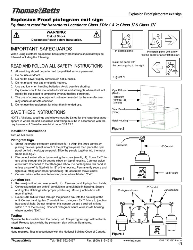
Explosion Proof pictogram exit sign Explosion Proof pictogram exit sign Equipment rated for Hazardous Locations: Class I Div.1 & 2; Class II & Class III WARNING: Risk of Shock. Disconnect Power before Installation. IMPORTANT SAFEGUARDS Pictogram panel When using electrical equipment, basic safety precautions should always be followed including the following: READ AND FOLLOW ALL SAFETY INSTRUCTIONS 1. 2. 3. 4. 5. 6. All servicing should be performed by qualified service personnel. Do not use outdoors. Do not let power supply cords touch hot surfaces. Do not mount near gas or electric heaters. Use caution when handling batteries. Avoid possible shorting. Equipment should be mounted in locations and at heights where it will not readily be subjected to tampering by unauthorized personnel. 7. The use of accessory equipment not recommended by the manufacturer may cause an unsafe condition. 8. Do not use this equipment for other than intended use. Pictogram panel with arrow Flip the panel for arrow left (below) Install the panel with the person going to the right. Figure 1 Opal Diffuser (Back) Pictogram Panel(s) (2) (Middle) SAVE THESE INSTRUCTIONS Clear Panel (Front) NOTE : All plugs, couplings and elbows must be Listed for the hazardous atmosphere in which the unit is installed and wiring must be in accordance with the requirements of Canadian electrical code CSA 22.1. Metal Housing Figure 2 Installation Instructions Turn off AC power. Pictogram Sign 1. Select the proper pictogram panel (see fig.1). Align the three panels by placing the clear panel in front of the pictogram panel then place the opal panel behind the pictogram panel. Slide the panels together into the metal frame (see fig.2). 2. Disconnect swivel elbow by removing the screw (see fig. 4). Route EXIT fixture wires through the 90-degree elbow on top of housing. Connect swivel elbow with 6" conduit to the 90-degree elbow. Do not lengthen this conduit unless a seal-off is fitted within 18" of the housing. Permanently secure and tighten all fitting after proper positioning. Re-assemble swivel elbow. 3. Connect wires in the remote transfer panel where labeled "Exit”. Exit wires 6” Conduit Exit Fixture Figure 3 Junction box 1. Remove junction box cover (see fig. 4). Remove conduit plugs from inside. 2. Connect junction box with 6" conduit into conduit hole in housing. Secure and tighten all fittings after proper positioning. Mount junction box with mounting feet. 3. Route EXIT fixture wires through the junction box into the housing of the unit. Connect and tighten 6" conduit from pictogram EXIT fixture to junction box conduit hole. Do not lengthen this conduit unless a seal-off is fitted within 18” of the housing. Connect pictogram fixture wires inside housing where labelled "Exit". 6” Conduit 90 degree elbows Junction box Testing Operate the test switch from the battery unit. The pictogram sign will be illuminated. Release test switch, the pictogram sign will stay illuminated. Maintenance None required. Test in accordance with the National Building Code of Canada. Thomas&Betts Tel: (888) 552-6467 Figure 4 Fax: (800) 316-4515 www.tnb.com 10/12 750.1697 Rev A 1/1


