Forehearth burner - OXY-THERM® FH
3 - 18.5 - 3
E - i - 5/13
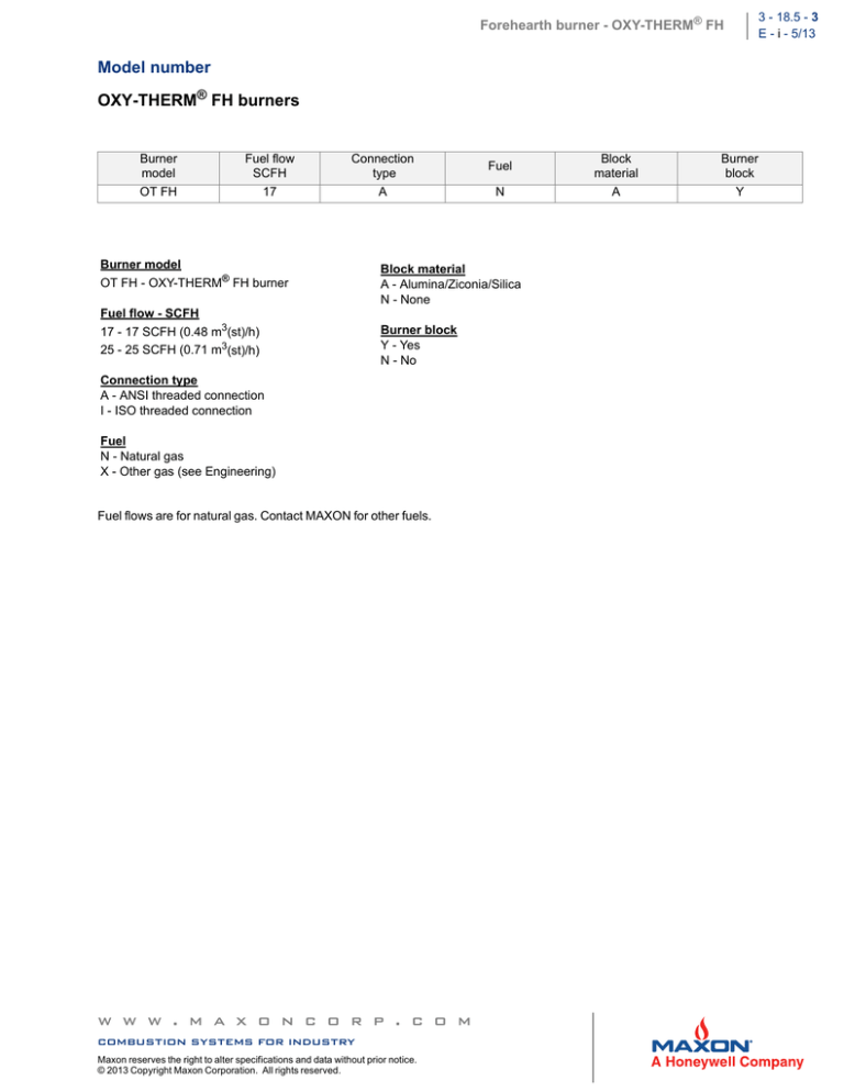
Model number
OXY-THERM® FH burners
Burner
model
OT FH
Fuel flow
SCFH
17
Connection
type
A
Burner model
OT FH - OXY-THERM® FH burner
Fuel flow - SCFH
17 - 17 SCFH (0.48 m3(st)/h)
25 - 25 SCFH (0.71 m3(st)/h)
Fuel
N
Block material
A - Alumina/Ziconia/Silica
N - None
Burner block
Y - Yes
N - No
Connection type
A - ANSI threaded connection
I - ISO threaded connection
Fuel
N - Natural gas
X - Other gas (see Engineering)
Fuel flows are for natural gas. Contact MAXON for other fuels.
w w w . m a x o n c o r p . c o m
combustion systems for industry
Maxon reserves the right to alter specifications and data without prior notice.
© 2013 Copyright Maxon Corporation. All rights reserved.
Block
material
A
Burner
block
Y
3 - 18.5 - 4
E - i - 5/13
Forehearth burner - OXY-THERM® FH
Specifications
Capacities
OXY-THERM® FH burners
Typical burner data
Fuel: natural gas at 60°F with 1000 Btu/ft3 (st) HHV - sg = 0.6 [1]
propane at 60°F with 2500 Btu/ft3 HHV - sg 1.57 [1]
Stated pressures are indicative. Actual pressures are a function of air humidity, altitude, type of fuel and gas quality.
OXY-THERM® FH burners
Maximum capacity range
Turndown
Pressures required to burner inlet for
maximum capacities
Typical oxygen to fuel
volumetric ratios
Approximate flame size
KBtu/h
Oxygen
Natural gas
Propane
To natural gas
To propane
Width
Length
psig
psig
inches
inches
OXY-THERM® FH burner size
FH 17
FH 25
17
25
4 to 1
1.0
1.0
Contact MAXON
2.05
5.1
2.5
3
12 - 14
16 - 18
[1] sg (specific gravity) = relative density to air (density air = 0.0763 lb/ft3 (st) )
Materials of construction
Burner part
Block material
Burner insert assembly
Material
Alumina/Zirconia/Silica (AZS)
304/310/321 stainless steel
w w w . m a x o n c o r p . c o m
combustion systems for industry
Maxon reserves the right to alter specifications and data without prior notice.
© 2013 Copyright Maxon Corporation. All rights reserved.
Forehearth burner - OXY-THERM® FH
3 - 18.5 - 5
E - i - 5/13
Intended service and typical application
Application details
OXY-THERM® FH burners are designed for glass forehearths and other high temperature applications where self ignition and
flame supervision are not required. Applications using oxygen-fuel burner technology can vary greatly. Design specifics for
individual applications are provided by OEM or end user.
Process temperatures
OXY-THERM® FH burners may be applied at temperatures up to 3050°F (1680°C) with standard block materials. Minimum
operating process temperature is 1382°F (750°C).
Removal of the burner nozzle is recommended when the burner is out of service in an operating forehearth or other application.
Cooling flow, either clean, dry air or oxygen, must be used whenever the burner assembly is in a high temperature atmosphere and
is not firing. See installation and operating instructions for more details.
NOTE: Premium-quality materials have been used in the OXY-THERM® FH burner, but metal components
can be destroyed by high temperatures if the burner is misused or disconnected from cooling flows.
Because most oxygen-fuel burner applications operate at very high temperatures, these guidelines focus
on enhancing burner performance and longevity.
Burner blocks
The material used in the refractory block is an alumina/zirconia/silica composition. It is the responsibility of the user to assure its
compatibility with the user’s process.
Ratio control requirements
Oxygen-fuel burners require accurate control of both fuel and oxygen for optimum performance. MAXON recommends the use of
SMARTLINK® electronic fuel/air ratio control system. Piping should include control valves for both oxygen and fuel. In addition,
flow meters for oxygen and fuel capable of local or remote readout are recommended for proper burner adjustment.
Emission performance
Emissions performance will vary by application. Contact MAXON for information on installation-specific estimates and guaranteed
values. No guarantee of emissions is intended or implied without specific, written guarantee from MAXON.
w w w . m a x o n c o r p . c o m
combustion systems for industry
Maxon reserves the right to alter specifications and data without prior notice.
© 2013 Copyright Maxon Corporation. All rights reserved.
3 - 18.5 - 6
E - i - 5/13
Forehearth burner - OXY-THERM® FH
Dimensions and weights
OXY-THERM® FH burners
H
D 1
C
B
A
E 2
F
A
G
1) Oxygen inlet
2) Gas inlet
J
K
D
A
B
C
3
3.4
1.5
ANSI
1/8-27
NPT
Dimensions in inches unless stated otherwise
E
F
G
H
ISO
ANSI
ISO
Rc 1/828
1/8-27
NPT
Rc 1/828
10.0
11.9
11.2
J [1]
K [2]
Burner
weight
lbs
Block
weight
lbs
8.8
10.2
1.2
9
[1] Burner removal clearance required
[2] Burner gas tube removal clearance required
w w w . m a x o n c o r p . c o m
combustion systems for industry
Maxon reserves the right to alter specifications and data without prior notice.
© 2013 Copyright Maxon Corporation. All rights reserved.
Forehearth burner - OXY-THERM® FH
3 - 18.5 - 7
E - i - 5/13
Installation instructions
Please read the operating and mounting instructions before using the equipment. Install the equipment in
compliance with the prevailing regulations.
Bedrijfs- en montagehandleiding voor gebruik goed lezen! Apparaat moet volgens de geldende voorschriften
worden geïnstalleerd.
Lire les instructions de montage et de service avant utilisation! L’appareil doit imperativement être installé selon
les règlementations en vigueur.
Betriebs- und Montageanleitung vor Gebrauch lesen! Gerät muß nach den geltenden Vorschriften installiert
werden.
Storage
OXY-THERM® FH burners shall be stored dry (inside). Burner blocks have been cured carefully before shipment and shall be kept
dry. Wetting of the blocks could result in premature failures.
Handling
OXY-THERM® FH burners are shipped as complete units. Handle burners with care, using proper equipment, during unpacking,
transport, lifting and installation. Any impact on the burner could result in damage.
Piping
Use care when connecting fuel tubing/piping to the burner fuel connection. Fuel connection is not designed to support fuel piping. Fuel and oxygen piping must be supported to prevent undue stress and damage to burner block and components.
Flexible connections are recommended. Refer to recommended piping and support diagram.
If multiple burners are fed from a single fuel and oxygen train, care should be taken to equalize fuel and oxygen delivery to each
burner.
Every component that comes in contact with oxygen must be cleaned for oxygen service.
Burner mounting
The primary objective is to seal all openings between the burner and wall and to support the weight of any
system piping. The burner block sits on the sill or wall.
The block must rest flat on the sill or wall without rocking to allow the weight to be evenly distributed. Failure to do so could result in
cracking or block failure. If burner openings are too large, shims may be used to align the burner. Avoid applying any compressive
or tensile forces to the ceramic portions of the burner as this may cause premature failure.
The burner opening should provide a minimum of 1/16” clearance on all three sides. High temperature furnace sealant or packing
should be used between the burner and wall.
OXY-THERM® FH burners are designed to fire horizontally and should be mounted accordingly.
w w w . m a x o n c o r p . c o m
combustion systems for industry
Maxon reserves the right to alter specifications and data without prior notice.
© 2013 Copyright Maxon Corporation. All rights reserved.
3 - 18.5 - 8
E - i - 5/13
Forehearth burner - OXY-THERM® FH
Typical burner mounting arrangement
Note: Wall structure removed from above illustration for clarity
1) Use pipe and
clamp on fuel
gas line to keep
nozzle pressed
into block
opening
1
w w w . m a x o n c o r p . c o m
combustion systems for industry
Maxon reserves the right to alter specifications and data without prior notice.
© 2013 Copyright Maxon Corporation. All rights reserved.
Forehearth burner - OXY-THERM® FH
3 - 18.5 - 9
E - i - 5/13
Cooling air flow
Removal of the burner nozzle is recommended when the burner is out of service. If removal is not possible, or not chosen, cooling
flow, either clean, dry air, nitrogen or oxygen, must be used. Typical compressed air systems contain lubrication oils, which will
contaminate oxygen-clean environments and cannot be used for cooling flows without special treatment. Cooling air provided by
plant process air fans is one possible source.
Ratio adjustment
Oxygen-fuel burners require accurate control of both fuel and oxygen for optimum performance. MAXON can supply state-of-theart electronic or manual oxygen/fuel ratio control valves. Piping should include control valves for both oxygen and fuel. In addition,
flow meters for oxygen and fuel capable of local or remote readout are suggested for proper burner adjustment.
Cold installation procedure
Read the entire installation procedure before proceeding with the installation of oxygen-fuel burners.
Failure to follow the proper installation sequence noted below could result in damage or destruction of
vital burner components. Cooling oxygen or air flows should be present at all times when the burner
housing and metal components are mounted to a hot forehearth.
Visually inspect the burner.
Refer to page 3-18.5-6 for burner mounting dimensions and refer to page 3-18.5-7 and 8 for burner mounting instructions.
Install burner block into opening.
Complete connections for fuel and oxygen.
If the burner nozzles will be installed during heat up, confirm that cooling air or oxygen is available at the individual burner ports
and control stations before installing the burner.
If burner nozzles are not installed, place ceramic wool into the burner block opening to prevent hot gases from escaping during
heat-up procedure.
Install the burner nozzle assembly into the opening.
Burner installation is complete.
Other system safeguards and approvals must be completed before the burner can be lit. These safeguards include, but are not
limited to: 1) furnace operating temperature at the burner location must exceed the ignition temperature of the fuel being used;
and 2) oxygen/fuel control must be functional and characterized to provide the proper oxygen/fuel ratio to the burner.
Hot installation procedure
Read the entire Cold Installation Procedure (as a reference) before proceeding with the installation of oxygen-fuel burners.
Failure to follow the proper installation sequence noted below could result in damage or destruction of
vital burner components. Cooling oxygen or air flows should be present at all times when the burner nozzle
is inserted.
All moisture within the burner block should be removed before starting installation. Preheating burner block to remove moisture and reduce thermal shock is advised.
Where the new burner block contacts older or hot materials, silica paper should be used as a thermal buffer. The burner opening should be clean and free of debris.
Insert the burner block into the burner opening.
Insert burner nozzle into block, ensuring cooling air or oxygen flows are established to protect metal components.
Allow the new burner block to heat up to near ambient temperatures (usually about one half to three-quarters of an hour).
Resume normal operations as described in Cold Installation Procedure.
w w w . m a x o n c o r p . c o m
combustion systems for industry
Maxon reserves the right to alter specifications and data without prior notice.
© 2013 Copyright Maxon Corporation. All rights reserved.
3 - 18.5 - 10
E - i - 5/13
Forehearth burner - OXY-THERM® FH
Operating instructions
Instructions provided by the company or individual responsible for the manufacture and/or overall installation of a complete system incorporating MAXON burners take precedence over the installation and operating instructions provided by MAXON. If any of the instructions provided by MAXON are in conflict with local
codes or regulations, please contact MAXON before initial start-up of equipment.
Read the combustion system manual carefully before initiating the start-up and adjustment procedure.
Verify that all of the equipment associated with and necessary to the safe operation of the burner system
has been installed correctly, that all pre-commissioning checks have been carried out successfully and
that all safety-related aspects of the installation are properly addressed.
Start-up
Checks during and after start-up
During and after start-up, check the integrity of the system. Check all threaded connections after first firing (first time on
temperature) and retighten if necessary.
Burner ignition
CAUTION: The OXY-THERM® FH burner does not have self ignition capability. It is the responsibility of the
end user and service personnel attempting start-up to confirm that ignition temperatures appropriate for
the fuel used are present inside the furnace where the burner is located. In cases where manual ignition
from the outside is required, provisions shall be made in the furnace wall adjacent to the burner. Burners
should be started up at minimum fuel and oxygen flows (see capacity table on page 3-18.5-4) to prevent
sudden pressure rise in the fired chamber.
Set correct gas and oxygen flow before attempt of burner ignition. Flow meters for oxygen and gas flow measurement should be
used for proper burner adjustment.
CAUTION: Oxygen should only be used with approved materials, properly cleaned pipe and equipment,
and specially designed systems. Ordinary materials can be extremely flammable in the presence of oxygen
and air enriched with oxygen.
Maintenance instructions
Safety requirements
Regular inspection, testing and recalibration of combustion equipment according to the installation manual is an integral part of its
safety. Inspection activities and frequencies shall be carried out as specified in the installation manual.
Visual inspections
Regular visual inspection of all connections (oxygen and gas piping to the burner) and burner flame size and aspect are essential.
Spare parts
It is recommended to keep local stock of burner spare parts if burner is critical to continued process operations. Consult your
MAXON sales representative for burner spare parts and system accessories.
w w w . m a x o n c o r p . c o m
combustion systems for industry
Maxon reserves the right to alter specifications and data without prior notice.
© 2013 Copyright Maxon Corporation. All rights reserved.


