Analysis of deviations in Autoclave curing of fiber Composite
advertisement
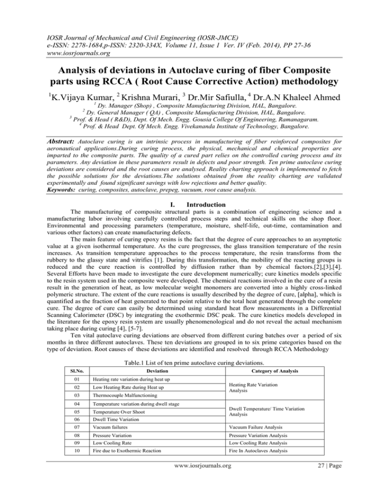
IOSR Journal of Mechanical and Civil Engineering (IOSR-JMCE) e-ISSN: 2278-1684,p-ISSN: 2320-334X, Volume 11, Issue 1 Ver. IV (Feb. 2014), PP 27-36 www.iosrjournals.org Analysis of deviations in Autoclave curing of fiber Composite parts using RCCA ( Root Cause Corrective Action) methodology 1 K.Vijaya Kumar, 2 Krishna Murari, 3 Dr.Mir Safiulla, 4 Dr.A.N Khaleel Ahmed 1 Dy. Manager (Shop) , Composite Manufacturing Division, HAL, Bangalore. Dy. General Manager ( QA) , Composite Manufacturing Division, HAL, Bangalore. 3 Prof. & Head ( R&D), Dept. Of Mech. Engg. Gousia College Of Engineering, Ramanagaram. 4 Prof. & Head Dept. Of Mech. Engg. Vivekananda Institute of Technology, Bangalore. 2 Abstract: Autoclave curing is an intrinsic process in manufacturing of fiber reinforced composites for aeronautical applications.During curing process, the physical, mechanical and chemical properties are imparted to the composite parts. The quality of a cured part relies on the controlled curing process and its parameters. Any deviation in these parameters result in defects and poor strength. Ten prime autoclave curing deviations are considered and the root causes are analysed. Reality charting approach is implemented to fetch the possible solutions for the deviations.The solutions obtained from the reality charting are validated experimentally and found significant savings with low rejections and better quality. Keywords: curing, composites, autoclave, prepeg, vacuum, root cause analysis. I. Introduction The manufacturing of composite structural parts is a combination of engineering science and a manufacturing labor involving carefully controlled process steps and technical skills on the shop floor. Environmental and processing parameters (temperature, moisture, shelf-life, out-time, contamination and various other factors) can create manufacturing defects. The main feature of curing epoxy resins is the fact that the degree of cure approaches to an asymptotic value at a given isothermal temperature. As the cure progresses, the glass transition temperature of the resin increases. As transition temperature approaches to the process temperature, the resin transforms from the rubbery to the glassy state and vitrifies [1]. During this transformation, the mobility of the reacting groups is reduced and the cure reaction is controlled by diffusion rather than by chemical factors.[2],[3],[4]. Several Efforts have been made to investigate the cure development numerically; cure kinetics models specific to the resin system used in the composite were developed. The chemical reactions involved in the cure of a resin result in the generation of heat, as low molecular weight monomers are converted into a highly cross-linked polymeric structure. The extent of the cure reactions is usually described by the degree of cure, [alpha], which is quantified as the fraction of heat generated to that point relative to the total heat generated through the complete cure. The degree of cure can easily be determined using standard heat flow measurements in a Differential Scanning Calorimeter (DSC) by integrating the exothermic DSC peak. The cure kinetics models developed in the literature for the epoxy resin system are usually phenomenological and do not reveal the actual mechanism taking place during curing [4], [5-7]. Ten vital autoclave curing deviations are observed from different curing batches over a period of six months in three different autoclaves. These ten deviations are grouped in to six prime categories based on the type of deviation. Root causes of these deviations are identified and resolved through RCCA Methodology Table.1 List of ten prime autoclave curing deviations. Sl.No. Deviation Category of Analysis 01 Heating rate variation during heat up 02 Low Heating Rate during Heat up 03 Thermocouple Malfunctioning 04 Temperature variation during dwell stage 05 Temperature Over Shoot 06 Dwell Time Variation 07 Vacuum failures Vacuum Failure Analysis 08 Pressure Variation Pressure Variation Analysis 09 Low Cooling Rate Low Cooling Rate Analysis 10 Fire due to Exothermic Reaction Fire In Autoclaves Analysis Heating Rate Variation Analysis Dwell Temperature/ Time Variation Analysis www.iosrjournals.org 27 | Page Analysis of deviations in Autoclave curing of fiber Composite parts using RCCA ( Root Cause II. Root Cause Analysis Root Cause Analysis (RCA) is a method for assessing problems based on their root causes. It analyzes the underlying factors in any given adverse reaction to identify a problem's source and corrective measures to fix it.[8]. This process is unique, as it delves deeper to find answers based on hidden causes and their effects, rather than merely looking at the most apparent. RCA is a structured process designed to help people understand the causes of past problems for the purpose of preventing recurrence. It is step-wise and structured so that it can be consistently applied to different problems at different times by different people. Root Cause Analysis has been utilized in many different industries for the past three decades, originating in the field of engineering. It has expanded its reach to aerospace, transportation, nuclear power and chemical processing, pollution control, information technology and manufacturing. Root Cause Analysis & Corrective Action is a tool that leads to cultural change in an organization to enhance better quality and productivity. In this paper the Apollo Root Cause Analysis method is utilized to analyze and solve the curing deviations. 2.1 : Heating Rate variation during curing of metal tool composite parts in autoclave. Heat up rate varies between the lagging and the leading thermocouple with a thermal gradient of 20 30 deg.C as shown in the cure chart Fig.1.The lagging thermocouple takes more time to reach the required temperature meanwhile the leading thermocouple reaches the hold/ dwell state. Thereby the leading thermocouple continues to hold in the same temperature until the lagging thermocouples reach the required dwell temperature. This deviation result in resin degradation and in poor compaction . Analysis has done using reality charting to find out the root causes for heat up rate variation as shown in the Fig.2 Lagging Thermocouple Leading Thermocouple Fig.1 Cure chart shows lagging and leading thermocouples during heating stage with a thermal gradient of 20 deg.C. Fig. 2 Root causes for heating rate variation depicted using reality chart. www.iosrjournals.org 28 | Page Analysis of deviations in Autoclave curing of fiber Composite parts using RCCA ( Root Cause The possible root causes for heating rate variation are obtained using reality charting, they are 1.parts with different metal tools and varying thickness are cured in a batch 2. improper loading of tools in the autoclave 3.operating autoclave in manual mode. The solution for each root cause is arrived for the primary effect by assessing the possible solutions and assigning a rank based on its impact on the problem (A – solution that avoids the reoccurrence of the problem, B- solution that partially avoids the reoccurrence of the problem,Csolution that may/can avoid the problem) as shown in the table 2. Table.2 Possible solutions for heating rate variation. Causes Solutions Study the thermal conductivity of each tool material. Tool material/ Geometry / size Improper loading in autoclave Rank B Study the thermal profile of each tool material by conducting tool thermal survey. A Group the tools as per the thermal survey report to achieve uniform heat up rate. A Study each tool thickness and group as per the thickness B Study the tool geometry and size from the tool data B Large size and thick tools to be loaded at door end and the air flow path to be ensured. A Small size tools are to be positioned at fan end. C Tool thickness within 5 mm variation is to be loaded in a batch. A Grouping of tools based on its thermal behavior and loading in an autoclave is an essential task to be considered to maintain the thermal uniformity. Since the air turbulence is high at the door end the temperature will be high compared to the fan end, hence lager area and thick parts are recommended to load at the door end. meanwhile clear air path should be maintained in the tools for air circulation in the autoclave. The above points are implemented in ten cure cycles and the heating rate variation is avoided completely,It is found the heat up rate is maintained within the tolerance of +/- 5 deg.C as shown in the cure chart Fig. 3. Fig.3 Cure chart shows thermal profile during heating stage within a thermal gradient of 5 deg.C. 2.2. Vacuum Failures during curing process. Vacuum plays a vital role during gelation stage in curing process, low vacuum levels may result in low ILSS values and deficiencies in the cured part like white patches, voids etc. All the parts which are cured in autoclaves are vacuum bagged using thin high temperature resistant bagging film, usually some tools have inbuilt vacuum lines to apply sufficient vacuum to the bag and some tools are connected with vacuum valves to apply vacuum. Vacuum bags fail during curing process as shown in the Fig 4.at different stages of the cure cycle. www.iosrjournals.org 29 | Page Analysis of deviations in Autoclave curing of fiber Composite parts using RCCA ( Root Cause Vacuum Failure Fig4. Vacuum failures during curing of composite structures. . Fig.5 Root causes for the vacuum failures shown in compact mode using reality charting. Parts after vacuum bagging will undergo leak check process, where the leak rate is ensured and recorded, the allowable leak rate is 50 milli bar for 5 min. it is noticed that the vacuum bag fails suddenly or gradually. The root causes for the gradual and sudden vacuum bag failures is carried in step 1 as shown in the Fig. 6. Step 1 Fig.6. Root causes for the vacuum bag burst shown in compact mode using reality charting. www.iosrjournals.org 30 | Page Analysis of deviations in Autoclave curing of fiber Composite parts using RCCA ( Root Cause Fig.7 Thermocouple pulls out during curing process. It is found from the analysis the gradual vacuum bag leak is due to the vacuum hose PTFE inner tube problem which gets damaged after 20 – 30 curings when they are exposed to elevated temperatures at 180 deg.C for 2 -3 hours duration, also vacuum leaks are noticed in composite tools as well as the vacuum valve fittings. The sudden drop in vacuum is due to the vacuum bag puncture during the curing process and the root causes as analyzed form the reality charting are 1. Thermocouple pulls out during elevated temperatures due to air turbulence and tension in the thermocouple wire also at that point the sealant viscosity is low to avoid bag damage. Sometimes due to presence of dust particles are the carbon deposits inside the autoclave are prone to sudden vacuum bag fail. Vacuum failures can occur due to improper bagging and lack of technician skill and knowledge, where vacuum valves are not positioned above breather/bleeder, the inbuilt vacuum lines are blocked during lay up or insufficient folds are provided at corners to avoid bridging etc., the root cause analysis is carried and shown in Fig. 8. Fig.8 Root causes for the improper vacuum bagging shown in compact mode using reality charting. The possible solutions are obtained for each root cause as shown in the Table 3. It is found the solutions marked with rank „A‟ are the mandatory checks that needs to be implemented to avoid total vacuum bag failures during curing process. www.iosrjournals.org 31 | Page Analysis of deviations in Autoclave curing of fiber Composite parts using RCCA ( Root Cause Table 3. Possible solutions obtained for vacuum failures during curing . Causes Vaccum Bag Burst Improper Vacuum Bagging Solutions Ensure the Vacuum hoses for leak before connecting part Rank A Study the tool history card and discard the tool if it is found leak. A Reset the vacuum lines in Autoclave before start of cure. A Ensure the SLE of vacuum bagging materials and sealant B Ensure the absence of dust particles or FOD inside autoclave. B Ensure proper length of thermocouples to avoid pull out due to air turbulence. B Proper folds are ensured to avoid bridging in parts A Ensure the Vacuum valves are placed in right position over the breather / bleeder to avoid resin block in valves. B Ensure the leak rate before loading it in to autoclaves for curing process. A 2.3 Dwell Temperature / Time Variation Dwell temperature increases gradually as the curing progress as shown in the fig 9. this deviation in curing results in improper dwell time and temperature exceeds maximum dwell temperature limit. The root causes are analyzed and depicted using reality chart in custom view as shown in Fig. 8. Fig.8 Root causes for the dwell time / temperature variation in custom mode using reality charting. Dwell temperature variation. Fig.9 cure chart that shows the dwell temperature / time variation during curing process. It is inferred from the root cause analysis that the causes for the dwell temperature variation is due to the precooling problem in the autoclave where the controller fails to maintain the steady temperature during dwell stage and hence the air temperature gradually increases during the process the part temperature increases continuously without maintaining the required dwell period. www.iosrjournals.org 32 | Page Analysis of deviations in Autoclave curing of fiber Composite parts using RCCA ( Root Cause Table 4. Possible solutions obtained for Dwell Temperature / Time variation during curing Causes Heating Rate Variation Solutions Grouping and mapping of tools as per the tool material, size and geometry. Rank A Check for programming/ controller errors before the start of cure. Check for precooling is functioning in autoclave. Pre Cooling Problem Check for Inlet water temperature in tank. A B It is inferred from the analysis and the cure charts, if metal tool parts are cured in a batch the heating rate varies between the lagging and the leading thermocouples which results in improper dwell time as the leading thermocouple completes 20 – 30 min dwell before the lagging thermocouple reaches the dwell point. This leads to large variation of thermal gradient and dwell time variation, hence the tools are to be grouped based on their thermal survey data and loaded on the trolley to achieve uniform heat up rate and dwell period. 2.4 Pressure Variation during curing process. Pressure is an important curing parameter to control the consolidation and residual stress in curing composite parts. During curing process in autoclaves as the heating takes place the pressure gradually increases since it is directly proportional to the temperature, at the same time during cooling stage the pressure decreases, the pressure controller has to regulate the pressure to maintain the uniform pressure level throughout the cure cycle. Generally the reservoir pressure is kept twice than the autoclave applied pressure so as to operate the pneumatic valves & solenoid valves during cooling or application of pressure, sometimes due to unavoidable situations the reservoir pressure drops below the applied pressure in the autoclave, which results in curing deviations. The root causes for the pressure variation is analysed as shown in the Fig. 10. Sometimes in curing sandwich parts pressure variation leads to core crush. Fig.10 Root causes for the pressure variation in compact view using reality charting. Fig.11 cure chart that shows the pressure variation during curing process. www.iosrjournals.org 33 | Page Analysis of deviations in Autoclave curing of fiber Composite parts using RCCA ( Root Cause Table 5. Possible solutions obtained for pressure variation during curing Causes Solutions Rank Pressure Controller failed Ensure the pressure controller is calibrated and functioning properly before the start of cure cycle. A Solenoid valve / pressure regulator valve failed Ensure the periodic maintenance of the solenoid valves A Compressor failed to build pressure Ensure the periodic maintenance of the compressor, Install the stand by compressor or interlink the other compressor lines to maintain the regular flow of air to reservoir A The corrective action is to ensure the pressure controller / solenoid valves calibrated periodically every three months and its working condition is ensured before the start of every cure cycle, at the same time standby compressors are to be installed or all the reservoirs and the compressors should be interlinked to maintain the continuous air flow. Periodic maintenance schedule and monitoring should be implemented for compressors. 2. 5. Low Cooling Rate. Cooling in fibre / epoxy curing process is an important stage where the residual stress in the parts due to elevated temperatures are removed gradually so as to avoid the spring back effects, distortions, warpage etc. Usually the cooling is done at a rate of 2 to 3 o C/min under pressure and can be at low vacuum levels. But due to Heat exchangers inefficiency the cooling rate cannot be maintained as per the requirement. The root causes for the low cooling rate is analysed as shown in the Fig. 12. Fig. 12 Root causes for the Low Cooling rate in compact view using reality charting. From the analysis it is observed the use of hard water choke the heat exchanger tubes with scale formation which results in low water flow and discharge from the heat exchanger. Also the water inlet temperature measures high around 60- 70 deg.C due to inefficiency of the condensers fitted to the cooling water tanks. Fig.13 cure chart that shows the low cooling rate during curing process www.iosrjournals.org 34 | Page Analysis of deviations in Autoclave curing of fiber Composite parts using RCCA ( Root Cause From the cure chart in the Fig.13 the cooling rate is 0.75 deg.C/min as against the minimum requirement of 1 deg.C/min. Table 6. Possible solutions obtained for Low cooling rate in autoclaves. Causes Solutions Rank Heating Exchanger inefficiency Heat exchanger preventive maintenance schedule to be planned and descaling of Heat Exchanger tubes to be done. A Check for the solenoid valve working condition. A Low water discharge Check for cooling pump efficiency and the water level in cooling tank. B 2.6. FIRE IN AUTOCLAVES Exothermic reaction occurs during polymerisation of fiber/ epoxy composite curing; any epoxy resin should contain hardener which is mixed with resin in the right proportion. Hardener in the resin acts like an accelerator to control the cure reaction during curing process. Some resins are cure at room temperatures particularly the resins used in wet lay up but some resins are cured at elevated temperatures approximately around 120 o C to 180 o C based on the hardener property. Usually exothermic reaction during autoclave curing can be traced easily as the part thermocouple reads beyond the air temperature, and the operator can avoid problems due to exothermic reaction like fire in autoclave. The root cause analysis for the fire in autoclaves is analysed with the help of reality charting as shown in the Fig.15 It is observed through root cause analysis that the different resins have different gel temperatures and verification temperatures also found that the life expired resins always leads to exothermic reaction and thick parts with more number of layers need to be precompacted before taking up for curing to avoid the exothermic reactions. Fig.14 cure chart that shows the exothermic reaction during curing process Fig. 15 Root causes for the Fire in autoclaves in compact view using reality charting. www.iosrjournals.org 35 | Page Analysis of deviations in Autoclave curing of fiber Composite parts using RCCA ( Root Cause Table 7. Possible solutions obtained for the fire in Autoclaves. Causes Exothermic Reaction Cure cycle deviation Solutions Ensure the SLE of the prepeg and other materials used for vacuum bagging. Ensure the precompaction operation for every 12 layers or introduce low heating rates during curing with multiple dwell periods. Ensure the absence of inflammable materials inside the autoclave before the start of curing process. Ensure the maximum temperature. pressure is set in the cure cycle program and ensures the cycle number for particular resin type. Ensure the over trip temperature controller is set and is active. III. Rank A A A A B Results And Discussions. Root causes and the corrective remedies for the deviations are obtained from the reality charting and the solutions are assessed experimentally that owe to the following results. 1. 2. 3. 4. 5. 6. Heating rate with Uniform tools found within ± 5 o C and also it is observed that their ILSS (Inter Laminar Shear Strength) values are within limits. Grouping of parts for loading in to autoclave in a batch is framed based on their tool material type, thickness and resin type.Thick parts with more number of layers are debulked at RT and precompacted in autoclaves at near gel temperatures before taken up for final curing. Proper vacuum bagging and leak check should be ensured before loading the part in to the autoclave to avoid the vacuum failures to a great extent besides the vacuum valves are to be positioned properly to avoid the resin block during curing process, and vacuum hoses are to be ensured for zero vacuum leak. Heating rate and the precooling in the autoclave are the main factors for dwell time /temperature variation that needs to be closely monitored and controlled. Heat exchanger efficiency plays a vital role in controlling the cooling rate besides the cooling lines and the water conditions are to be monitored to avoid the cooling rate problems. Compressor efficiency and the pressure controllers are to be ensured for sufficient flow of air pressure during curing process, it is recommended to interconnect all the compressor lines to maintain a steady flow of the air pressure even a compressor fails during curing process. Use of life expired prepegs, resin, bagging materials will cause exothermic reactions during elevated temperatures that may lead to fire in autoclaves, it is suitable to use nitrogen in autoclaves as pressure medium to avoid fire. IV. Conclusions This work has explored the root causes and the possible solutions to eliminate the prime curing deviations of composite parts in industrial autoclaves. Efforts are made for an in depth analysis of each root cause in a structured and scientific way with the use of RCCA (Root Cause & Corrective Action) methodology. In this paper Apollo reality charting is used to a great extent to identify the root causes and the possible solutions that are assessed experimentally. The solutions are recommended for each cause to avoid its reoccurrence. This work deals with the six prime deviations and the same methodology can be implemented for resolving any of the autoclave curing deviations. This work will be used for the designers and the composite production engineers to optimise the curing process and to accomplish better quality products. The experimental results achieved from this work owed to a significant savings and better productivity. References [1]. [2]. [3]. [4]. [5]. [6]. [7]. [8]. Neeraj Rai, Ranga Pitchumani (1997) “ Optimal cure cycles for the fabrication of thermosetting-matrix composites” Department of Mechanical Engineering, University of Connecticut, U-139 Storrs, Connecticut 06269-3139. N. Ersoy, K. Potter, M.R. Wisnom, and M.J. Clegg, Compos. A (2005), 36, 1700 . P. Hubert, A. Johnston, A. Poursartip, and K. Nelson,(2001) "Cure Kinetics and Viscosity Models for Hexcel 8552 Epoxy Resin," in A Materials and Processes Odyssey, 46th International SAMPE Symposium and Exhibition, Long Beach, CA, May 6-10. L. Sun, S.-S. Pang, A.M. Sterling, I.I. Negulescu, and M.A. Stubblefield, J. Appl. Polym. Sci., 83, 1074(2002). M. Buczek, D. Mason, C.W. Lee, and A. Saunders, (1999) "Proactive Control of Curing Composites," in Proceedings of the 44th International SAMPE Symposium, Long Beach, CA, J. Player, M. Roylance, W. Zukas, and D.K. Roylance, (Nov .2000)"UTL Consolidation and Out-of-Autoclave Curing of Thick Composite Structures," in 32nd International SAMPE Technical Conference, Boston,MA,757, P. Hubert, A. Johnston, A. Poursartip, and K. Nelson ,(2005) "Cure Kinetics and Viscosity Models for Hexcel 8552 Epoxy Resin," in A Materials and Processes Odyssey, 46th International SAMPE Dean.L Gano (2013) “ Seven Steps to effective problem solving & strategies for personal success”e-book published by Apollonian Publications, USA. www.iosrjournals.org 36 | Page
