HF DF - HFIA, High Frequency Industry Association
advertisement

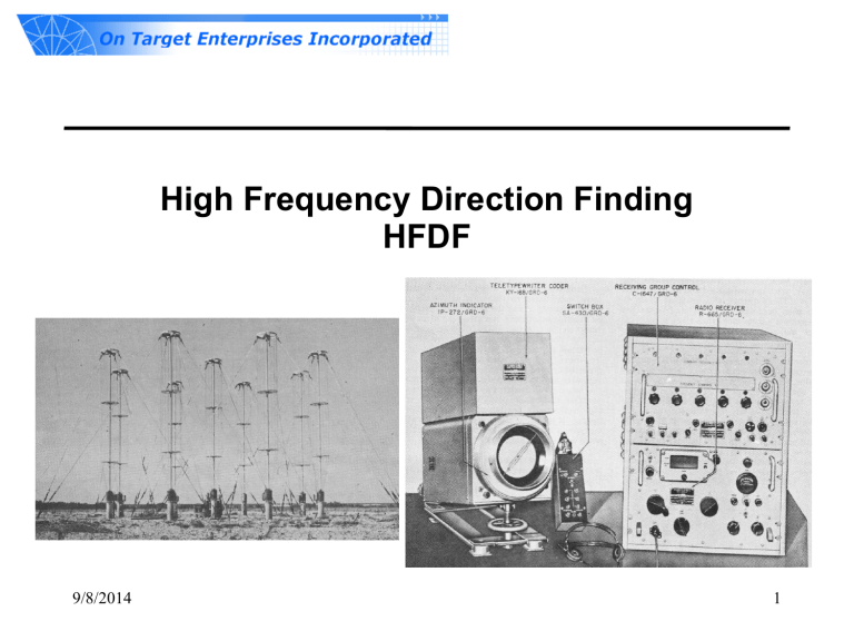
High Frequency Direction Finding HFDF 9/8/2014 1 On Target Enterprises Overview • • • • Woman-Owned Small Business Cocoa Florida Main Office Receiver development laboratory System test ranges – 500 acre open field range in Colorado – 15 acre jungle range in Florida • Products – MISER: UHF/VHF detect/DF/record – WATCHDOG: HF detect/DF/map/record – SentryGo: Marine Navigational Radar detect/DF/characterize 9/8/2014 2 Direction Finding • • • • • What is Direction? Azimuth and or Elevation Polarization Time (or time difference) Frequency (or frequency difference) • Vector Space – Complex difference of signals between antennas 9/8/2014 3 Applications of HF Direction Finding • Finding sources of interference to communications • Locating transmitters – – – – • • • • Hostile forces Amateur radio contest beacons Distress signals FCC or ITU violations Understanding the ionosphere Deep space mapping Maximizing receive/transmit link quality SETI LOFAR Array 9/8/2014 4 Classic Challenges to HF DF • High interference • Long wavelength (large footprint) • Propagation variance – – – – Atmosphere and Ionosphere Time delay, Doppler Polarization rotation, birefringence Aggregate propagation paths • Multipath • Wide fractional bandwidth 9/8/2014 5 Tactical HF DF Challenges • “Tactical” systems need to be – – – – • Light weight, low power Economical Rugged, repairable Quick to deploy, easy to use HF DF systems must exhibit – Sensitivity to weak signals (requiring large antennas) – Large dynamic range (requiring significant power) Conflicting Requirements • In the presence of high interference across large bandwidth – Channel measurement accuracy (to determine “direction”) • Requiring large separation between antennas – Some method of calibration • To angle and polarization 9/8/2014 6 Technologies Applicable to Modern HF DF • Active Antennas – Small, E or H field, no mutual impedance • Fast Analog to Digital Converters (ADC) – Low power, high precision • High speed data acquisition, transfer, storage – USB, Ethernet, • Fast Digital Signal Processing (DSP) – Special purpose hardware, software, FPGAs • Widely distributed time synchronization • Wide area/bandwidth networking 9/8/2014 7 The HFDF Process Design receiver network Tactical Readjustment H2 Deploy V1 Task receivers V2 H1 Detect H0 Measure complex response across channels V3 H3 Interpret against antenna calibration Model ionosphere Display results on map 9/8/2014 8 On Target Enterprises Services • • • • System analysis Conceptual design Proof of concept Critical element demonstration Products • • • • • • • • • 9/8/2014 Tactical radio detection and DF HF, UHF/VHF, microwave Small, lightweight, modular, rugged Low cost per unit Broadband access – Wideband continuously – Narrowband precision tasking Power solutions; battery, solar, shore Real-time monitoring and recent activity logging Integrated processing and laptop GUIs Field level – Array configuration – Software module interaction – Networking – Troubleshooting, repair 9 HF System Modules • N-Wideband channels (50 MHz) – Coherent, time-synchronized, snapshot processing – 1 to 3 KHz frequency resolution • M-Narrowband channels (11kHz to 200 kHz) – Slaved to wideband system – Coherent, time-synchronized, continuous processing – Arbitrary frequency resolution • Worldwide tactical mapping – Array planning, site selection, accuracy prediction – Real time tactical display – Playback with customized processing of multichannel narrowband • TDOA/FDOA narrowband time-tagging – Correlation processing – Self calibration, maintenance, and ionospheric monitoring from ionosondes • Polydimensional analyzer (PolyAna) 9/8/2014 10 Possible Deployment Active V-pol Antenna Element • Polarization and array spacing driven by frequency range of interest • Deployed, calibrated by two people in 1 hour • Small SUV transportable • 24/7 operation with solar/batteries Active H-pol inverted-vee turnstyle element 9/8/2014 11 Possible Operating Modes Frequency dependent threshold Composite Spectrum showing rich signal density Real-time full HF spectrum monitoring - DF all signals simultaneously - Adjustable threshold vs frequency - Detections, DFs, etc. stored - Self triggered narrow band analysis Falling raster display Multi-day environment analysis - Display every signal hit with DF - More than two weeks of data storage - Narrowband analysis overlays Date and Time Radio Frequency 9/8/2014 12 Possible Operating Modes Multiple sites commanded into narrowband beamforming mode - Simultaneous time-coherent collection scheduled - Correlation processing applied to map energy density - Low cost massive aperture deep space array 9/8/2014 13 System Performance and Accuracy Performance measure • • • • • • Sensitivity Amplitude, phase accuracy Wavefront angle accuracy Incident polarization Solution delay Transmitter location solution 9/8/2014 Limiting Aspects • Noise • Interference • Signal Characteristics – Frequency, bandwidth – Transmitting power – Up-time – A-priori knowledge – Movement • Selection of array elements and geometry • Ionosphere characteristics and model – Real-time updates – Processing power – O vs. X propagation modes • Inter-system network bandwidth • Number of systems deployed • Ability to relocate receivers • Observables measured and processed • System calibration 14 Mapping Interface 9/8/2014 15 Thank You • John Hoover – john@ontargetenterprises.com 9/8/2014 16


