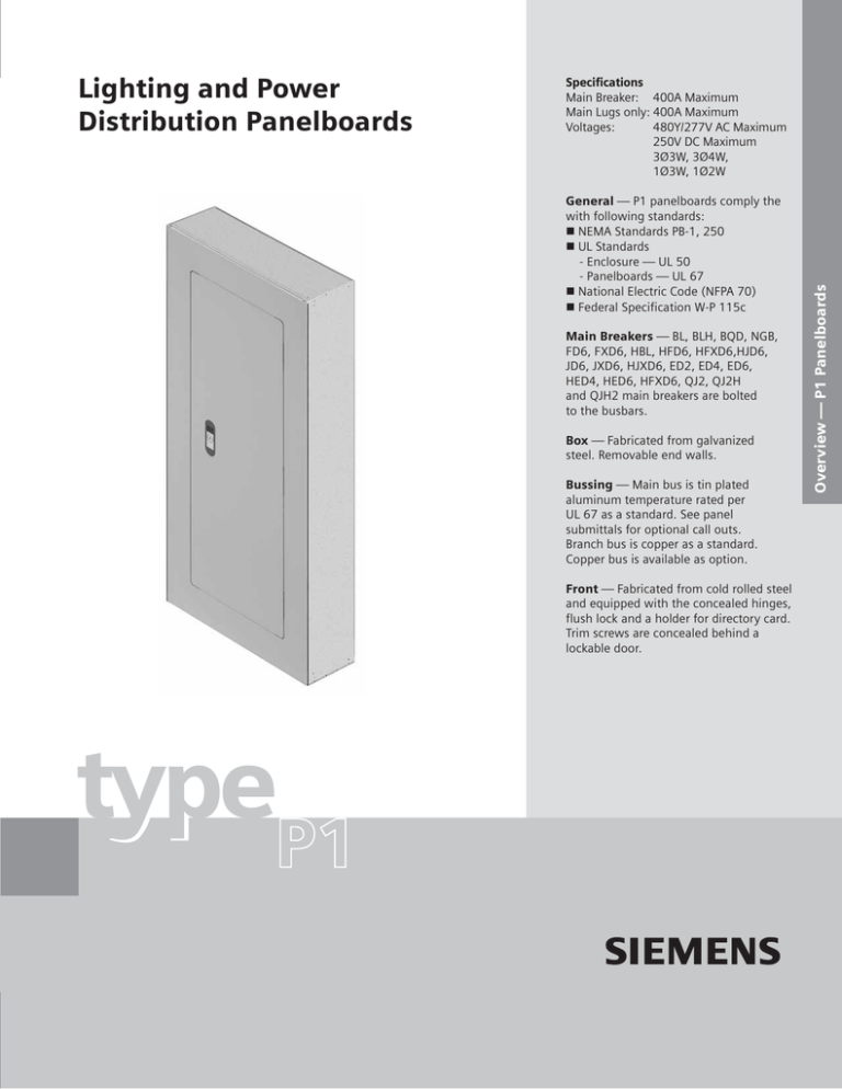
Specifications
Main Breaker: 400A Maximum
Main Lugs only: 400A Maximum
Voltages:
480Y/277V AC Maximum
250V DC Maximum
3Ø3W, 3Ø4W,
1Ø3W, 1Ø2W
General — P1 panelboards comply the
with following standards:
NEMA Standards PB-1, 250
UL Standards
- Enclosure — UL 50
- Panelboards — UL 67
National Electric Code (NFPA 70)
Federal Specification W-P 115c
Main Breakers — BL, BLH, BQD, NGB,
FD6, FXD6, HBL, HFD6, HFXD6,HJD6,
JD6, JXD6, HJXD6, ED2, ED4, ED6,
HED4, HED6, HFXD6, QJ2, QJ2H
and QJH2 main breakers are bolted
to the busbars.
Box — Fabricated from galvanized
steel. Removable end walls.
Bussing — Main bus is tin plated
aluminum temperature rated per
UL 67 as a standard. See panel
submittals for optional call outs.
Branch bus is copper as a standard.
Copper bus is available as option.
Front — Fabricated from cold rolled steel
and equipped with the concealed hinges,
flush lock and a holder for directory card.
Trim screws are concealed behind a
lockable door.
type
P1
Overview — P1 Panelboards
Lighting and Power
Distribution Panelboards
Main Lug or Main Breakers
Maximum
Ampere Rating
Main Breaker
Types
Maximum
Number of Poles
BL, BLH
HBL
BQD
NGB
100
125
ED2, ED4
ED6, HED4
HED6
QJ2
QJH2
QJ2-H
FXD6
FD6
HFD6, HFXD6
MLO
225
250
18
30
42
≤250
JD6, JXD6,
HJD6,
HJXD6
MLO
400
18
30
42
Side Gutter Wiring Space
Inches (mm) (Fig. P1-1)
Box Height
Inches (mm)
Connectors Suitable
for Cu or Al
32 (813)
38 (965)
44 (1118)
32 (813)
38 (965)
44 (1118)
32 (813)
38 (965)
#8-#6 AWG Cu or Al
#8-6 AWG Cu or #8-4 AWG Al
#8-#1 AWG Cu or #6-#1/0 AWG Al
15-30 amp #14-#6 Cu or #12-#6 Al
35-125 amp #6-1/0 Cu. #4-2/0 Al
#14-#10 AWG Cu or #12-10 AWG Al
#3-3/0 Cu or
44 (1118)#1-2/0 Al
#6 AWG-300 Kcmil (Cu)
or
#4 AWG-300 Kcmil (Al)
#6 AWG-350 Kcmil (Cu)
or
#4 AWG-350 Kcmil (Al)
32 (813)
38 (365)
44 (1118)
32 (813)
38 (365)
44 (1118)
32 (813)
38 (365)
44 (1118)
56 (1422)
62 (1575)
68 (1727)
56 (1422)
62 (1575)
68 (1727)
(1) #4 - 350 Kcmil
3/0-500 Kcmil (Cu)
or
4/0-500 Kcmil (Al)
(1) 250-600 Kcmil
or
(2) #3/0 - 500 Kcmil
Fig. P1-1
Reference
Letter
Panel
Width 20”
Panel
Width 24”
Optional
A
B
C
D
E
F
6.375 (162)
5.500 (140)
5.000 (127)
6.125 (156)
6.500 (165)
5.250 (133)
8.375 (213)
7.500 (191)
7.000 (178)
8.125 (206)
8.500 (216)
7.250 (184)
A
Main Device Gutter
BL, BLH, HBL
BL, BLH, HBL
≤ 250A - MB
A
BLF, BLHF
BLF, BLHF
B
BQD
BQD
B
C
NGB
NGB
C
D
400A-MB
All MLO
ED2, ED4, ED6, HED4, HED6
E
QJ2, QJH2, QJ2-H
F
FXD6, FD6, HFD6
Panel Width
20 in. (508 mm)
Subfeed mounting limit 1 per panel.
Main Breaker Gutter Dimensions Inches (mm)
Main Breaker
BL, BLH, HBL, BQD
ED2, ED4, ED6, HED4
QJ2, QJH2, QJ2-H
FD6, FXD6, HFD6
JD6, JXD6 Gutter
20” wide box
8.500 (216)
6.125 (156)
6.500 (165)
5.250 (133)
15.000 (381)
24” wide box
10.500 (267)
8.125 (206)
8.500 (216)
7.250 (184)
15.000 (381)
Neutral Location
20” wide box
11.500 (292)
11.500 (292)
11.500 (292)
11.500 (292)
26.750 (680)
JD frame mounted vertically.
Typical Panelboard Wiring Diagrams
Main Breaker
1 Phase, 3 Wire
Main Breaker
3 Phase, 4 Wire,
3 Phase, 3 Wire (No SN)
Main Lugs
1 Phase, 3 Wire
Main Lugs
3 Phase, 4 Wire,
3 Phase, 3 Wire (No SN)
Breaker Mounting Kit – Main or Subfeed w/o Breaker
200% Neutral Lug Kits – 250A
Amp
Rating
No. of
Circuits
Breaker Frames
BL, BLH, HBL
100
BQD
NGB
125
ED2, ED4, ED6, HED4, HED6
QJ2, QJH2, QJ2-H
225
FXD6, FD6, HFD
250
JD2, JD6, JXD6, HJD6, HJXD6
400 Service
1 Phase
3 Phase
3 Phase
1 Phase
3 Phase
1 Phase
3 Phase
1 Phase
3 Phase
1 Phase
3 Phase
1 Phase
3 Phase
Catalog
Number
MBKBL1
MBKBL3
MBKBC3
MBKNB1
MBKNB3
MBKED1
MBKED3
MBKQJ1
MBKQJ3
MBKFD1
MBKFD3
MBKJD1
MBKJD3
18
30
42
Amp
Rating Material
No. of
Circuits
Al
250
Cu
Al
400
Cu
Catalog
Service Number
(1) #6 AWG-350 Kcmil (Cu or Al)
(1) #6 AWG-350 Kcmil (Cu or Al)
(1) #6 AWG-350 Kcmil (Cu or Al)
(1) #6 AWG-350 Kcmil (Cu or Al)
(2) 3/0 - (1) 600 Kcmil
(2) 3/0 - (1) 600 Kcmil
(2) 3/0 - (1) 600 Kcmil
(2) 3/0 - (1) 600 Kcmil
1 Phase
3 Phase
1 Phase
3 Phase
1 Phase
3 Phase
1 Phase
1 Phase
MLKA1
MLKA3
MLKC1
MLKC3
4MLKA1
4MLKA3
4MLKC1
4MLKC3
2NLK30
2NLK42
Catalog
Number
Description
2 Branch Neutral Strips,
4 Main Neutral Lug, Hardware
2 Branch Neutral Strips,
4 Main Neutral Lug, Hardware
2 Branch Neutral Strips,
4 Main Neutral Lug, Hardware
18
42
Wire Range
2NLK18
200% Neutral Lug Kits – 400A
30
Lug Kits – Main or Feed-thru
Catalog
Number
Description
2 Branch Neutral Strips,
2 Main Neutral Lug, Hardware
2 Branch Neutral Strips,
2 Main Neutral Lug, Hardware
2 Branch Neutral Strips,
2 Main Neutral Lug, Hardware
42NLK18
42NLK30
42NLK42
Copper Neutral Lug Kits – 250A and 400A
No. of
Circuits
Catalog
Number
Description
2 Branch Neutral Strips,
1 Main Neutral Lug, Hardware
2 Branch Neutral Strips,
1 Main Neutral Lug, Hardware
2 Branch Neutral Strips,
1 Main Neutral Lug, Hardware
18
30
42
CNLK18
CNLK30
CNLK42
Branch Circuit Breakers
Max.
Amp
Rating
Breaker
Type
BL
BL HID
BLR
BLE
BLEH
BLF
100
BLHF
BGL BAF
BAFH
BLH
HBL
BQD
125
NGB No.
of
Poles
1
2
3
1
2
2
1
2
1
2
1
2
1
3
2
3
1
1
1
2
3
1
2
3
1
2
3
1
2
3
Amp
Rating
15 - 70
15 - 100
15 - 100
15 - 30
15 - 30
15 - 100
15 - 30
15 - 60
15 - 30
15 - 60
15 - 30
15 - 60
15 - 30
15 - 60
15 - 30
15 - 30
15, 20
15, 20
15 - 70
15 - 100
15 - 100
15 - 70
15 - 100
15 - 100
15 - 100
15 - 125
Maximum Interrupting Rating (kA)
Volts – AC
120
120/240 240
277 480
10
—
—
—
—
—
10
—
—
—
—
—
10
—
—
10
—
—
—
—
—
10
—
—
—
—
—
10
—
—
10
—
—
—
—
—
10
—
—
—
22
—
—
—
—
—
22
—
—
—
10
—
—
—
—
—
10
—
—
—
22
—
—
—
—
—
22
—
—
—
10
—
—
—
—
—
10
—
—
—
10
—
—
—
—
22
—
—
—
—
—
22
—
—
—
—
22
—
—
—
—
—
22
—
—
—
65
—
—
—
—
65
—
—
—
—
—
65
—
—
—
65
—
14
—
—
65
—
—
14
—
—
65
—
14
600
—
—
—
—
—
—
—
—
—
—
—
—
—
—
—
—
—
—
—
—
—
—
—
—
—
—
—
DC
250
—
—
—
—
—
—
—
—
—
—
—
—
—
—
—
—
—
—
—
—
—
—
—
—
14
14
14
100
—
—
—
—
—
14
—
—
—
100
100
—
100
100
25
—
—
—
25
25
Main Only
Two pole breaker is one phase and neutral. Three pole is two phase and neutral.
P1 panel with NGB branch devices will not accept BL or BQD frames in the same panel as branch devices.
NOTE: BL, HBL, BLH and BQD breakers are mounted in common mountings in 3” or (6) pole increments.
Load Connectors
15-20A
25-35A
40-50A
55-70A
80-100A
15-40A
45-100A
15-30A
35-125
#14-#10 AWG Cu
#12-#10 AWG Al
#8-#6 AWG Cu
#8-#6 AWG Al
#8-#6 AWG Cu
#8-#4 AWG Al
#8-#4 AWG Cu
#8-#2 AWG Al
#4-#1/0 AWG Cu
#2-#1/0 AWG Al
#14-#6 AWG Cu
#12-#6 AWG Al
#8-#1 AWG Cu
#6-#1/0 AWG Al
#14-#6 Cu
#12 - #6 Al
#6-1/0 Cu
#4-2/0 Al
Modifications and Dimensions
Panel Options, Enclosures
• Extra gutter to sides or ends of the can
• 24" wide boxes
• Hinged trims
• Door-in-door trims
• Screw to the box trims
• Trim mounted devices (Devices
mountedand wired to the trim should
also have hinged trim specified.)
- Pilot lights
- Toggle switches
- Push buttons
• Painted boxes
• Custom colors
• Increase gauge trims and boxes
• Stainless steel trims and boxes, Type 1
• Aluminum trims and boxes, Type 1
• NEMA 3R enclosures
• NEMA 3R/12 enclosures
• NEMA 4 enclosures
• NEMA 4X enclosures
• Special keyed locks
- TEY
- TEU1
- Cat 60
- LL803
- LL806
- Yale
• Meters
(Contact application engineering
for space requirements.)
• Panel skirts
• Gaskets between trim and box
Type P1Dimensions
Type 3R and 3R/12 Box
Type 1 Box (Box is Symmetrical)
Box To Wall
Mounting Holes
2 in.
[ 51 ]
.31 in.
[8]
7.5 in.
[ 191 ]
.50 in.
[ 13 ]
2 in.
[ 51 ]
4.63 in.
[ 118 ]
Mounting
Dimple
Interior To Box
Mounting
Stubs
Mounting
Bracket
32 in. 38 in. 44 in.
[ 816 ] [ 969 ] [ 1222 ]
햲앱
56 in. 62 in. 68 in.
[ 1428 ] [ 1581 ] [ 1734 ]
32 in. 38 in. 44 in.
[ 813 ] [ 965 ] [ 1118 ]
햲
56 in. 62 in. 68 in.
[ 1422 ] [ 1574 ] [ 1727 ]
2 in.
[ 51 ]
4.63 in.
[ 118 ]
12.63 in.
[ 321 ]
15 in.
[ 381 ]
2 in.
[ 51 ]
2 in.
[ 51 ]
5.75 in.
[ 146 ]
햲
20 in. 햲
[ 510 ]
21.5 in.
[ 546 ]
20 in.
[ 508 ]
1 in.
[25]
5.75 in.
[ 146 ]
햲
23.5 in.
[ 597 ]
햲
Flush Mounting
³⁄₄ in.
[19 ]
20 in.
[ 508 ]
³⁄₄ in.
[19 ]
5.75 in.
[ 146 ]
Dimensions are interior of the box. Add 5/8” to width for absolute dimension. Add 1/8” to height for absolute dimension. Dimensions shown in inches and
millimeters [ ].
Siemens Energy & Automation, Inc.
3333 Old Milton Parkway
Alpharetta, GA 30005
1-800-964-4114
info.sea@siemens.com
www.sea.siemens.com/power
©2007 Siemens Energy & Automation, Inc. All Rights Reserved
Siemens is a registered trademark of Siemens AG. Product names mentioned may be trademarks or registered
trademarks of their respective companies. Specifications are subject to change without notice.
PBSS-20301-0407 1M0407PP Printed in USA

