Blue Point
Engineering
Instruction
I
www.BPEsolutions.com
Pointing the Way to Solutions!
Motor Control by Relay
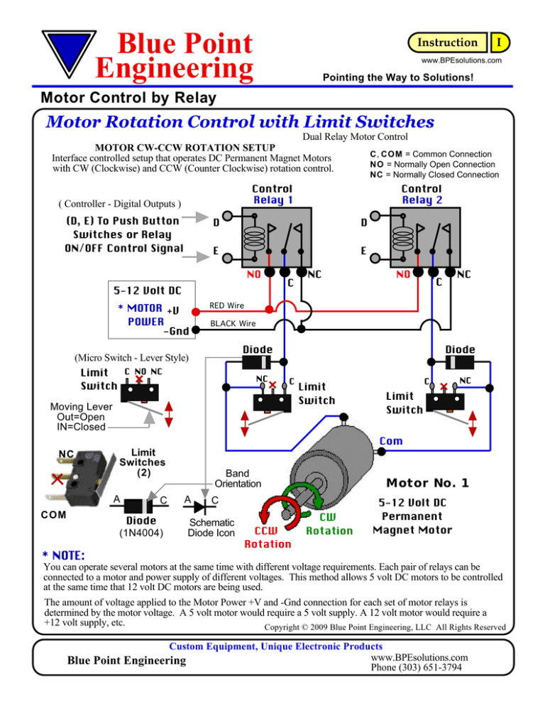
Motor Rotation Control with Limit Switches
Dual Relay Motor Control
MOTOR CW-CCW ROTATION SETUP
C, COM = Common Connection
Interface controlled setup that operates DC Permanent Magnet Motors
N O = Normally Open Connection
with CW (Clockwise) and CCW (Counter Clockwise) rotation control.
NC = Normally Closed Connection
Control
Relay 1
( Controller - Digital Outputs )
(D, E) To Push Button
Switches or Relay
ON/OFF Control Signal
D
D
E
E
NO
5-12 Volt DC
* MOTOR +V
POWER
-Gnd
Control
Relay 2
C
NC
NO
NC
C
RED Wire
BLACK Wire
Diode
(Micro Switch - Lever Style)
C NO NC
Limit
Switch
NC
Diode
C
Moving Lever
Out=Open
IN=Closed
Limit
Switch
C
NC
Limit
Switch
Com
NC
Limit
Switches
(2)
A
COM
C
Diode
(1N4004)
* NOTE:
Band
Orientation
A
Motor No. 1
C
Schematic
Diode Icon
CCW
Rotation
CW
Rotation
5-12 Volt DC
Permanent
Magnet Motor
You can operate several motors at the same time with different voltage requirements. Each pair of relays can be
connected to a motor and power supply of different voltages. This method allows 5 volt DC motors to be controlled
at the same time that 12 volt DC motors are being used.
The amount of voltage applied to the Motor Power +V and -Gnd connection for each set of motor relays is
determined by the motor voltage. A 5 volt motor would require a 5 volt supply. A 12 volt motor would require a
+12 volt supply, etc.
Copyright © 2009 Blue Point Engineering, LLC All Rights Reserved
Custom Equipment, Unique Electronic Products
www.BPEsolutions.com
Blue Point Engineering
Phone (303) 651-3794
Blue Point
Engineering
Instruction
I
www.BPEsolutions.com
Pointing the Way to Solutions!
Motor Control by Relay
Diode
(D, E) To Push Button Switches or
Relay - ON/OFF Control Signal
NC
MOTOR POWER
-Gnd
+V
Motor
No. 1
Limit
Switch-A
CW
Rotation
Limit NC
Switch-B
C
Motor
No. 1
ON
OFF
Diode
ON
D
Motor
Switch B
Status
ON
CCW or CW
ON
CW
OFF
Diode
CCW
NC
COM
COM
Relay 1
Relay 2
NO
Limit Switch Logic
Example1: Motor is rotating left (CCW) and hits limit switch. Limit
switch-A has now been activated, (Turned OFF) the motor has stopped
rotating to the left (CCW). No power is going to the motor now. To move
motor to the right (CW) the diode on Limit Switch -A now must conducts
current past the open switch to allow the motor to activate rotation
movement to the right (CW). The connected diode completes the
circuit, allowing current to flow one way. When the move right (CW)
command is received, (Relay activated) motor will move CW, since
diode is completing the circuit needs to power the motor. As the motor
moves away from the hit limit switch - A, the switch is reset to the
normal closed position, allowing current to flow back through the
switch, bypassing the diode now and setting the switch for the next hit
limit action.
Motor
NC
Limit
Switch
B
Limit
Switches (2)
Limit
Switch -A
Motor Logic
Trigger
ON / OFF
Motor Relay / Switch Logic
Motor
Relay 1
Relay 2
Status
Motor
OFF
OFF
STOP
No. 1
ON
CCW
OFF
OFF
ON
CW
ON
ON
STOP
C
COM
NOTE:
Limit Switches are wire as a Normal Closed connection
(NC). Power will flow through the switch until it has
been activated to the Open position (NO). On open
position NO power will flow to the connected device.
NC
E
Limit switches are used to stop a motor when it rotates to a specific
location or has moved a connected mechanical device to a specific
point and/or stops the motor from causing damage to itself or the
attached mechanical device being moved. When limit switches are in
the ON positions, the motor can rotate CW or CCW between the two
limit switches.
Limit Switch Logic
Switch A
E
NO
Diode
CCW
Rotation
RED Wire
D
C
BLACK Wire
Diode
This connection setup prevents the possibility of both relays from
shorting back into the power supply when both switched on.
Copyright © 2009 Blue Point Engineering, LLC, All Rights Reserved
Custom Equipment, Unique Electronic Products
www.BPEsolutions.com
Blue Point Engineering
Phone (303) 651-3794
Blue Point
Engineering
Instruction
I
www.BPEsolutions.com
Pointing the Way to Solutions!
Motor Control by Relay
Application
Example
WIZARD 4
Controller
WIZARD 2 Controller
Programmable
Relays
(Motor 1- Relays 1,2)
(Motor 2- Relays 3,4)
Relay
1
(Motor 1- Relays 1,2)
(Motor 2- Relays 3,4)
(Motor 3- Relays 5,6)
(Motor 4- Relays 7,8)
Relay
2
NO
C
4 Motors
NC
C
NO
NC
NC
MOTOR
+V
POWER
SUPPLY -Gnd
Limit
Switches
(2)
RED Wire
COM
BLACK Wire
Diode
(Micro Switch - Lever Style)
C NO NC
Diode
C
NC
Limit
Switch
Limit
Switch
C
NC
Limit
Switch
Com
Diode
(1N4004)
Diode
C, COM = Common Connection
N O = Normally Open Connection
NC = Normally Closed Connection
CCW
Rotation
CW
Rotation
Motor No. 1
5-12 Volt DC
Permanent Magnet
Motors
Motor No. 2
Copyright © 2009 Blue Point Engineering, LLC All Rights Reserved
Custom Equipment, Unique Electronic Products
www.BPEsolutions.com
Blue Point Engineering
Phone (303) 651-3794
Blue Point
Engineering
Instruction
I
www.BPEsolutions.com
Pointing the Way to Solutions!
Motor Control by Relay
Application
Example
Actual Travel
3-1/2"
Limi
1/2"
t Sw
itchs
2-3/8"
Hit Limit
Switchs
Limit
Switch (1)
Limit
Switch (2)
Limit
Switch
Switch
Lever
CW
5-12 Volt DC
Permanent Magnet
Motors
CCW
Motor No. 1
Limit
Switch
Copyright © 2009 Blue Point Engineering, LLC
All Rights Reserved
Custom Equipment, Unique Electronic Products
www.BPEsolutions.com
Blue Point Engineering
Phone (303) 651-3794


