EML 3005: Mechanical Design Gear Counter Shaft Design
advertisement

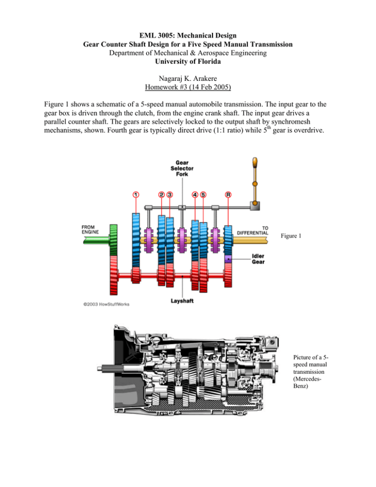
EML 3005: Mechanical Design Gear Counter Shaft Design for a Five Speed Manual Transmission Department of Mechanical & Aerospace Engineering University of Florida Nagaraj K. Arakere Homework #3 (14 Feb 2005) Figure 1 shows a schematic of a 5-speed manual automobile transmission. The input gear to the gear box is driven through the clutch, from the engine crank shaft. The input gear drives a parallel counter shaft. The gears are selectively locked to the output shaft by synchromesh mechanisms, shown. Fourth gear is typically direct drive (1:1 ratio) while 5th gear is overdrive. Figure 1 Picture of a 5speed manual transmission (MercedesBenz) Synchronizers 4 in dia gear Counter Shaft Dimensions 0.5 in 2.5 in 2.5 in 1st gear Diameter = d 3.0 in 3.0 in 2nd 19 in 3rd Gear Facewidth = 1 in 2.5 in 5th This project involves designing a 5-speed manual transmission gearbox. A manual transmission gearbox is a complex system involving many aspects of mechanical design. This project involves designing of the counter shaft alone, based on fatigue life, and bending and torsional stress requirements. Each group (of 5 students) will select a car or truck of their choice from a car magazine (Road & Track and Car & Driver, for example), or from the website of the car manufacturer. You are required to write a detailed design report and make a presentation detailing your gearbox design. The design report must present, at a minimum, the following information: • • • • • • Car selection, details such as weight, external dimensions, tire size, etc. Engine details (HP and torque ratings, Torque-Speed curve) Drag coefficient, Car frontal area calculations, estimated top speed. Equations used for calculating wind drag and rolling resistance, to calculate HP required at various speeds. Gear ratios selected for the 5-speed transmission, axle ratio selected. Design countershaft for infinite life. Select some points at near top-speed conditions. Make sure, based on your calculated HP requirements, that the car can indeed reach those speeds. Example Information for a Ford Mustang: Input gear diameter Car weight, W Tire diameter Tire pressure, P Car drag coefficient, Cd Car frontal area, Fa Max engine HP Max torque Rear axle ratio First gear ratio Second gear ratio Third gear ratio Fourth gear ratio Fifth gear ratio = 4 inch = 3,280 lb = 25.7 inch = 44 psi = 0.36 = 27 square ft. = 260 @ 5250 rpm = 302 lb-ft @ 4000 rpm = 3.27 = 3.37 = 1.99 = 1.33 = 1.00 = 0.67 15 V 2 W Rolling resistance (lbf) = 0.50 + + 0.0035 P P 100 Wind Drag (lbf) = 0.00256* Cd * Fa *V 2 HP = Total Resistance (lbf) * (V mph * 22/15)/550 Where V = car speed in MPH Total Resistance = Rolling resistance + Wind drag Design the worst-case counter shaft diameter, d, for infinite life. The counter shaft material is 4340 heat treated steel with Sy = 156 ksi and Sut = 170 ksi. Treat the gears on the shaft to be a sudden change in diameter and use suitable stress concentration factors Kt and Kf. If the shaft diameter turns out to be very large, use a material of higher strength from Appendix C (page 987 for alloy steels). For each gear, find the maximum bending moment and torque that can be transmitted by the gears and design the shaft for these maximum loads, for infinite life. Present the bending moment diagram for each gear. In the higher gears the max power/torque is typically at the max speeds, while at the lower gears max loads are at max acceleration conditions. List all the stress concentration factors used for all cases. Select the largest diameter from the worst case condition and use that as the design diameter. Assume a solid shaft.


