Design of controller for single axis knee using MR Damper
advertisement

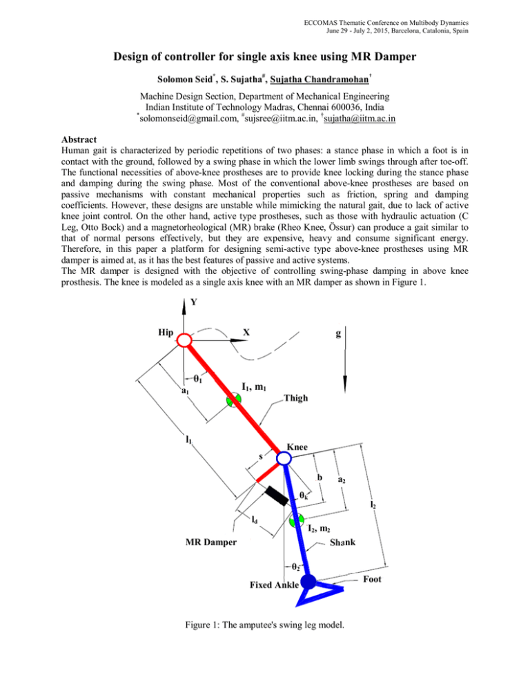
ECCOMAS Thematic Conference on Multibody Dynamics June 29 - July 2, 2015, Barcelona, Catalonia, Spain Design of controller for single axis knee using MR Damper Solomon Seid*, S. Sujatha#, Sujatha Chandramohan† Machine Design Section, Department of Mechanical Engineering Indian Institute of Technology Madras, Chennai 600036, India * solomonseid@gmail.com, #sujsree@iitm.ac.in, †sujatha@iitm.ac.in Abstract Human gait is characterized by periodic repetitions of two phases: a stance phase in which a foot is in contact with the ground, followed by a swing phase in which the lower limb swings through after toe-off. The functional necessities of above-knee prostheses are to provide knee locking during the stance phase and damping during the swing phase. Most of the conventional above-knee prostheses are based on passive mechanisms with constant mechanical properties such as friction, spring and damping coefficients. However, these designs are unstable while mimicking the natural gait, due to lack of active knee joint control. On the other hand, active type prostheses, such as those with hydraulic actuation (C Leg, Otto Bock) and a magnetorheological (MR) brake (Rheo Knee, Össur) can produce a gait similar to that of normal persons effectively, but they are expensive, heavy and consume significant energy. Therefore, in this paper a platform for designing semi-active type above-knee prostheses using MR damper is aimed at, as it has the best features of passive and active systems. The MR damper is designed with the objective of controlling swing-phase damping in above knee prosthesis. The knee is modeled as a single axis knee with an MR damper as shown in Figure 1. Y Hip X θ1 a1 g I1, m1 Thigh l1 Knee s b a2 θk ld l2 I2, m2 Shank MR Damper θ2 Fixed Ankle Figure 1: The amputee's swing leg model. Foot ECCOMAS Thematic Conference on Multibody Dynamics June 29 - July 2, 2015, Barcelona, Catalonia, Spain The ankle is assumed to be rigid. The parameters of the damper are determined through optimization of the prosthesis knee angle with a desired knee angle trajectory obtained from experimental data in normal level walking. Experimental data of thigh and hip motions are introduced as input into a dynamic system to find out a set of control parameters. The swing leg of the amputee is modeled as a two-link rigid body chain representing the thigh and the shank in sagittal plane motion. In the figure, subscripts 1 and 2 represent the thigh and shank respectively, mi are masses, ai are the distances of the mass centres from the respective proximal joints, Ii are the moments of inertia, li are lengths and θi are the absolute angles of thigh and shank from the vertical; s is the offset between the knee centre and location of attachment of MR damper piston on the thigh, θk = θ1 – θ2 is the knee angle, ld is the length of the MR damper and b is the distance between the knee centre and location of the MR damper attachment on the shank. The general dynamic motion equation can be written as: ( ) ̈ + , ̇ + ( )= (1) where ( ) ∈ × is the inertia matrix, C θ, θ̇ ∈ R × consists of the centripetal and Coriolis torques, G(θ) ∈ R × consists of the gravitational torque and the hip acceleration terms and Γ ∈ R × consists of the input torque matrix. Due to the highly nonlinear dynamic properties of the MR damper, system identification is mandatory for accurate control. In this work, the most commonly used model, modified Bouc-Wen, proposed by Spencer et al. [1] has been used. Based on this model, eleven control parameters that govern the hysteretic force and displacement of the damper have been identified. The experimental data for normal hip, thigh and shank motions are taken from Winter [2]. The control parameters of the MR damper should be selected such that the knee angle trajectory for the swing phase should match that of a normal person and this is achieved by feeding an appropriate input current to the damper. This involves formulating an optimization problem, which will minimize the error between expected knee angle (θke) from experimental data and computed knee angle (θkc) from the dynamic equation of motion. The values of the control parameters are evaluated for 1.5A input current (maximum operational current in active mode). Subsequently using optimal control parameters, the performance of the controller for zero input current (passive mode) is checked. Moreover, taking into account possible variations in the hysteretic characteristics of the MR damper, the lower and upper values of control parameters are selected and used as constraints. The objective function for the optimization is minimization of R(y) subject to Lower limits ≤Control parameters ≤ Upper limits. Here ( ) = ∫ θ (y, t) − θ (t) dt (2) where t0 and tf are the start and end times of the swing phase. A computer simulation is carried out in MathematicaTM. Comparison of the desired knee angle with that of the knee angle obtained from control parameters of the designed MR damper shows the effectiveness of the present design. Also, using the optimal control parameters, knee angle trajectory at zero input current has been computed and the result obtained shows a satisfactory performance of the system while operating in the passive mode, i.e., representing circumstances when the battery turns off. References [1] B. F. Spencer, S. J. Dyke, M. K. Sain and J. D. Carlson. Phenomenological model for magnetorheological dampers. ASCE Journal of Engineering Mechanics, Vol. 123, No. 3, pp.230238, 1997. [2] D. A. Winter. The Biomechanics and Motor Control of Human Gait: Normal, Elderly and Pathological. University of Waterloo Press, Waterloo, 2005.


