Understanding SCR Power Controls
advertisement
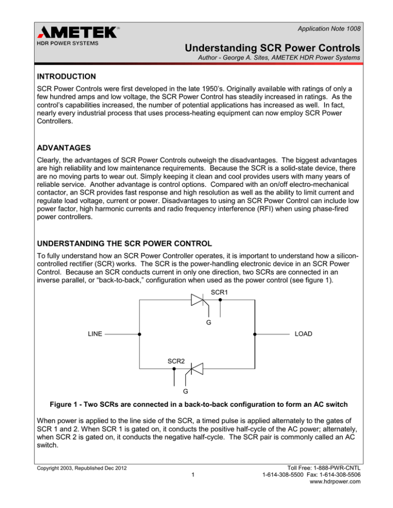
Application Note 1008 Understanding SCR Power Controls Author - George A. Sites, AMETEK HDR Power Systems INTRODUCTION SCR Power Controls were first developed in the late 1950’s. Originally available with ratings of only a few hundred amps and low voltage, the SCR Power Control has steadily increased in ratings. As the control’s capabilities increased, the number of potential applications has increased as well. In fact, nearly every industrial process that uses process-heating equipment can now employ SCR Power Controllers. ADVANTAGES Clearly, the advantages of SCR Power Controls outweigh the disadvantages. The biggest advantages are high reliability and low maintenance requirements. Because the SCR is a solid-state device, there are no moving parts to wear out. Simply keeping it clean and cool provides users with many years of reliable service. Another advantage is control options. Compared with an on/off electro-mechanical contactor, an SCR provides fast response and high resolution as well as the ability to limit current and regulate load voltage, current or power. Disadvantages to using an SCR Power Control can include low power factor, high harmonic currents and radio frequency interference (RFI) when using phase-fired power controllers. UNDERSTANDING THE SCR POWER CONTROL To fully understand how an SCR Power Controller operates, it is important to understand how a siliconcontrolled rectifier (SCR) works. The SCR is the power-handling electronic device in an SCR Power Control. Because an SCR conducts current in only one direction, two SCRs are connected in an inverse parallel, or “back-to-back,” configuration when used as the power control (see figure 1). SCR1 G LINE LOAD SCR2 G Figure 1 - Two SCRs are connected in a back-to-back configuration to form an AC switch When power is applied to the line side of the SCR, a timed pulse is applied alternately to the gates of SCR 1 and 2. When SCR 1 is gated on, it conducts the positive half-cycle of the AC power; alternately, when SCR 2 is gated on, it conducts the negative half-cycle. The SCR pair is commonly called an AC switch. Copyright 2003, Republished Dec 2012 1 Toll Free: 1-888-PWR-CNTL 1-614-308-5500 Fax: 1-614-308-5506 www.hdrpower.com 1 Understanding SCR Power Controls An SCR Power Controller consists of one, two or three AC switches, depending on how many phases are being controlled. A single AC switch is used to control a single-phase load. When two AC switches are used, the load must be three-phase, three-wire connected. Three AC switches are used on threephase loads that are three- or four-wire connected. CONTROL MODES There are three basic control modes: on/off, zero-firing and phase-firing. On/off control is the simplest method – it merely duplicates the action of an electromechanical contactor. When a command signal is applied, the control turns on and conducts current. When the command signal is removed, the control turns off. 0% 25% 50% 75% 100% Figure 2 - Zero-firing provides proportional control by varying the number of cycles the SCR is on or off. Zero-firing control switches the SCRs on and off – much like on/off control – but this method incorporates proportional control. With this control mode, the number of “on” or “off” AC cycles is varied to maintain as steady a voltage to the load as possible while turning the power on and off. Figure 2 shows the on and off AC cycles associated with a zero-fired SCR Power Control. Application Note – 1008 Copyright 2003, Republished Dec 2012 2 Toll Free: 1-888-PWR-CNTL 1-614-308-5500 Fax: 1-614-308-5506 www.hdrpower.com 1 Understanding SCR Power Controls While effective, zero-firing is not suited for every application. Because zero-firing turns the SCR either completely on or off, the voltage applied to the load is either zero or full. This is not acceptable with an exotic load element such as molybdenum disilicide. Molybdenum disilicide’s resistance is nearly zero when cold, but increases with temperature. Ohm’s law shows that if zero-firing were used to control a molybdenum disilicide load element, large current surges would result each time the SCR was turned on when the element was cold. These current surges can damage SCRs and cause nuisance fuse blowing. This application would be better suited to phase-firing. Phase-firing provides infinitely variable control of voltage to the load – much like a light dimmer. Similar to zero-firing, with phase-firing, timed gate pulses are fed to the SCRs. But with this control mode, each of the two SCRs in an AC switch is turned on only for a portion of the half-cycle it is controlling (Figure 3). 0% 25% 50% 75% 100% Figure 3 - Zero-firing provides proportional control by varying the number of cycles the SCR is on or off. Application Note – 1008 Copyright 2003, Republished Dec 2012 3 Toll Free: 1-888-PWR-CNTL 1-614-308-5500 Fax: 1-614-308-5506 www.hdrpower.com 1 Understanding SCR Power Controls TYPES OF CONNECTED LOADS Two basic types of loads typically are connected to SCR Power Controls: resistive and inductive. A resistive load is purely resistive in nature: its resistance varies little (less than +/-20%) with time and temperature. Or, the resistance changes can be large – greater than +/-20%. If the load resistance change is small, a zero-fired controller is the right choice. By contrast, if the load resistance change is large – as with molybdenum disilicide or silicon carbide elements – a phase-fired SCR Power Controller is the correct choice. Inductive loads such as a transformer-coupled load can cause high in-rush currents when used with zero-firing. In this case, using a phase-fired controller allows the load voltage to ramp up and avoids large current surges. When selecting an SCR Power Controller, take the following 4 steps: 1. 2. 3. 4. Determine the type of load element and whether on/off, zero or phase-firing is required. Determine the line voltage and the number of phases to be controlled. If the load is three-phase, determine whether it is three-or four-wire connected. Calculate the maximum load current required at full output voltage, regardless of the desired load voltage. (SCRs can turn full on when not expected or, if the SCR fails shorted, full line voltage would be applied to the load.) Use the following formulas when calculating load current. 1-Phase 3-Phase Phase-firing can be used with nearly any load type; on/off and zero-fired control should only be used with resistive loads. One caution: The lower power factor, higher harmonic currents and radio frequency interference generated by the high rising waveforms associated with phase-firing can be a problem. Using zerofiring, if the load type allows, can eliminate these problems. CONCLUSION Most electrical heat control devices do not offer the flexibility, available with SCR Power Controls. Its flexibility, ease of application and reliability account for its popularity. Application Note – 1008 Copyright 2003, Republished Dec 2012 4 Toll Free: 1-888-PWR-CNTL 1-614-308-5500 Fax: 1-614-308-5506 www.hdrpower.com
