RF-ISee: Identify and Distinguish Multiple RFID Tagged Objects in
advertisement

RF-ISee: Identify and Distinguish Multiple RFID Tagged Objects in Augmented
Reality Systems
Jianqiang Sun† , Lei Xie† , Qingliang Cai† , Chuyu Wang† , Jie Wu‡ , and Sanglu Lu†
† State Key Laboratory for Novel Software Technology, Nanjing University, China
‡ Department of Computer Information and Sciences, Temple University, USA
†
Email: {lxie,sanglu}@nju.edu.cn, {SunJQ,caiqingliang,wangcyu217}@dislab.nju.edu.cn, ‡ jiewu@temple.edu
Abstract—In this paper, we leverage RFID technology to
label different objects with RFID tags, so as to realize the
vision of “show me what I see from the augmented reality
system”. We deploy additional RFID antennas to the COTS
depth camera and propose a continuous scanning-based scheme
to scan the objects, i.e., the system continuously rotates and
samples the depth of field and RF-signals from these tagged
objects. In this way, we can accurately identify and distinguish
multiple tagged objects, by pairing the tags with the objects
according to the correlations between the depth of field and
RF-signals. Our solution achieves an average match ratio of
91% in distinguishing up to dozens of tagged objects with a
high deployment density.
I. I NTRODUCTION
People nowadays start to leverage augmented reality
(AR) systems to obtain an augmented view in a real-world
environment. Specifically, users can effectively distinguish
multiple objects of different categories, e.g., a specified
object in the camera can be recognized as a vase, a laptop,
or a pillow based on its natural features. However, these
techniques can only offer a limited degree of distinctions
among different objects, since multiple objects of the same
type may have very similar features. Moreover, they cannot
provide more inherent information about these objects, e.g.,
the manufacturers and production date. Therefore, it is rather
difficult to provide these functions by purely leveraging the
AR technology.
The rise of RFID provides us with an opportunity to
effectively distinguish these objects, even if they belong to
the same brand and have the same features of appearance.
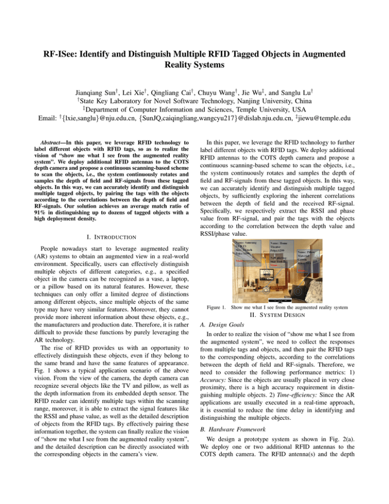
Fig. 1 shows a typical application scenario of the above
vision. From the view of the camera, the depth camera can
recognize several objects like the TV and pillow, as well as
the depth information from its embedded depth sensor. The
RFID reader can identify multiple tags within the scanning
range, moreover, it is able to extract the signal features like
the RSSI and phase value, as well as the detailed description
of objects from the RFID tags. By effectively pairing these
information together, the system can finally realize the vision
of “show me what I see from the augmented reality system”,
and the detailed description can be directly associated with
the corresponding objects in the camera’s view.
In this paper, we leverage the RFID technology to further
label different objects with RFID tags. We deploy additional
RFID antennas to the COTS depth camera and propose a
continuous scanning-based scheme to scan the objects, i.e.,
the system continuously rotates and samples the depth of
field and RF-signals from these tagged objects. In this way,
we can accurately identify and distinguish multiple tagged
objects, by sufficiently exploring the inherent correlations
between the depth of field and the received RF-signal.
Specifically, we respectively extract the RSSI and phase
value from RF-signal, and pair the tags with the objects
according to the correlation between the depth value and
RSSI/phase value.
Figure 1.
Show me what I see from the augmented reality system
II. S YSTEM D ESIGN
A. Design Goals
In order to realize the vision of “show me what I see from
the augmented system”, we need to collect the responses
from multiple tags and objects, and then pair the RFID tags
to the corresponding objects, according to the correlations
between the depth of field and RF-signals. Therefore, we
need to consider the following performance metrics: 1)
Accuracy: Since the objects are usually placed in very close
proximity, there is a high accuracy requirement in distinguishing multiple objects. 2) Time-efficiency: Since the AR
applications are usually executed in a real-time approach,
it is essential to reduce the time delay in identifying and
distinguishing the multiple objects.
B. Hardware Framework
We design a prototype system as shown in Fig. 2(a).
We deploy one or two additional RFID antennas to the
COTS depth camera. The RFID antenna(s) and the depth
Fig. 2(b) shows the software framework. The system is
mainly composed of three layers: the sensor data collection
layer, the middleware layer, and the application layer. For
the sensor data collection layer, the depth camera recognizes
multiple objects and collects the corresponding depth distribution, while the RFID system collects multiple tag IDs and
extracts the corresponding RSSIs or phases from the RFsignals of RFID tags. For the middleware layer, we sample
and extract some features from the raw sensor data, and
conduct an accurate matching among the objects and RFID
tags. For the application layer, the AR applications can use
the matching results directly to realize various objectives.
We respectively implement the following schemes:
1) Static Scanning via Depth-RSSI Pairing (SS-RSSI):
The system scans the tagged objects once at a fixed
position, and pairs the tags with the objects according
to their partial orders respectively in collected depth
and RSSI.
2) Hybrid Scanning via Depth-Phase Pairing (HSPhase): The depth camera continuously rotates and
scans the tagged objects, while the RFID antennas
scan the tagged objects once at a fixed position,
and pairs the tags with the objects according to the
extracted depth and phase.
3) Continuous Scanning via Depth-RSSI Pairing (CSRSSI): The system continuously scans the tagged
objects while it is rotating, and pairs the tags with
the objects according to the extracted series of depth
and RSSI.
4) Continuous Scanning via Depth-Phase Pairing (CSPhase): The system continuously scans the tagged
objects while it is rotating, and pairs the tags with
objects according to the extracted series of depth and
phase.
Application
RFID
Antennas
Matching
Algorithm
Rotating
Module
Middleware
Feature Sampling
and Extraction
Laptop
RSSI
Phase
Depth
RFID
Reader
Sensor data
collection
3D
Camera
(a) Prototype System
Figure 2.
RFID
System
(b) Software framework
System Framework
III. P ERFORMANCE E VALUATION
We evaluated our system using one Microsoft Kinect for
windows, one ImpinJ R420 reader, two Laird S9028 RFID
antennas, and multiple ImpinJ E41-B general purpose tags.
We deploy multiple objects in an area of about 3m× 3m,
and attach each tag to an object. We use the Kinect as the
depth-camera and use the RFID reader to scan the tags.
We run experiments to evaluate the accuracy in pairing
the tags with the objects. We evaluate the match ratio for
pairing different cardinalities of tagged objects. As shown
in Figure 3(a), as the cardinality of tagged objects increases
from 3 to 15, the match ratios of SS-RSSI and HS-Phase
decrease in a rapid approach, whereas the match ratios of
CS-RSSI and CS-Phase decrease slowly. We further evaluate
the time-efficiency via the number of samplings. As shown
in Figure 3(b), SS-RSSI achieves the least time delay, as
it only requires to scan once, whereas CS-RSSI achieves
the most time delay, as it requires to scan multiple times to
find the peak point via continuous scanning, HS-Phase and
CS-Phase achieve the medium time delay, as basically 3∼4
samplings are enough for them to estimate the position of
tagged objects.
1
0.8
0.6
0.4
0.2
0
SS−RSSI
HS−Phase
CS−RSSI
CS−Phase
3
5
10
15
The cardinality of tagged objects
The required number of samplings
C. Software Framework
AR Applications
3D-Camera
The match ratio
camera are fixed to a rotating shaft so that they can rotate
simultaneously. For the RFID system, we use the COTS
ImpinJ R420 reader, one or two Laird S9028 antennas, and
multiple Alien 9640 general purpose tags; for the depth
camera, we use the Microsoft Kinect for windows. They are
both connected to a laptop placed on the mobile robot. The
mobile robot can do a 360 degree rotation with the rotating
shaft. By attaching the RFID tags to the specified objects,
we propose a continuous scanning-based scheme to scan the
objects, i.e., the system continuously rotates and samples
the depth of field and RF-signals from these tagged objects.
In this way, we can obtain the depth of specified objects
from the depth sensor inside the depth camera, we can also
extract the signal features such as the RSSI and phase values
from the RF-signals of the RFID tags. By accurately pairing
these information, the tags and the objects can be effectively
bound together.
15
10
5
0
SS−RSSI HS−Phase CS−RSSI CS−Phase
(a) The match ratio for pairing dif- (b) The time delay for different
ferent cardinalities of tagged objects schemes
Figure 3.
The experiment results
ACKNOWLEDGMENTS
This work is supported in part by National Natural Science
Foundation of China under Grant Nos. 61472185, 61373129,
61321491, 91218302; JiangSu Natural Science Foundation,
No. BK20151390; EU FP7 IRSES MobileCloud Project
under Grant No. 612212; CCF-Tencent Open Fund. This
work is partially supported by Collaborative Innovation
Center of Novel Software Technology and Industrialization.
Lei Xie is the corresponding author.


