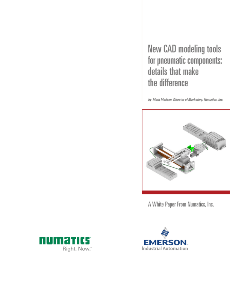
New CAD modeling tools
for pneumatic components:
details that make
the difference
by Mark Madsen, Director of Marketing, Numatics, Inc.
A White Paper From Numatics, Inc.
Introduction
Experienced engineers know that not all supplier CAD tools or the files they deliver are
created equal. When applying pneumatic automation components (cylinders, valve
manifolds, FRLs, etc.) to your product or system design, it pays to consider some defining
details of a prospective supplier’s Web-based CAD tool.
Does the site use neutral or true native file formats? Individual or assembled files? Part
numbers or attributes? And does it offer advanced ease-of-use features? How about
helpful error avoidance techniques?
New tools that get these decisive details right can save critical development time, make
your design experience significantly easier, and deliver higher-quality results.
1
File types: neutral versus native
The problems with the CAD design tools used by several major pneumatics manufacturers start with their output file formats. If they in fact offer CAD capabilities (some still do
not), some provide only neutral or translated CAD files, not true native files.
Such neutral, translated, or generic files (in formats such as DXF, IGES, or STEP) do allow
viewing via any popular CAD program, regardless of the system on which they were created. These files may also be adequate for analysis, measurement, development of cutter
paths, and other limited uses.
However, neutral files can only create “dumb” models, without associated parameters,
attributes, or histories. And despite some manufacturers’ claims, neutral files can often
be problematic to import and use. They almost always add extra time and trouble to your
design process. Some engineers find them so frustrating and error-prone, they actually
prefer to redraw a part instead of importing a neutral file!
2
By contrast, a true native CAD file imported into your CAD system might let you manipulate
the moving parts of an automation product such as a pneumatic cylinder. You can watch
the cylinder’s rod extend and retract in the CAD environment just as it would in physical
space — through the product’s full range of motion. So you can adjust your model to take
advantage of its precise motion constraints and its dimensions in various positions.
However, if you ran a neutral or translated file of the same cylinder, vital data would be
missing. The piston-moving feature would “break” — be unavailable for your use or calculation. Such files can also fail to correctly model “mates” (geometric relationships between
parts), can lose scalability or accurate dimensional data, might exhibit confusing “artifacts”
not present in the actual pneumatics component, and can drop part numbers. They make it
harder to properly verify design intent, perform assembly analysis, and ensure correct part
selection. So model building becomes a longer, more frustrating process. And the model
you create with a neutral file may lack critical features or functionality.
Many engineers now prefer a pneumatics manufacturer that insists on high-quality,
native-file Web tools instead. Example: via its Web-based CAD tool Numatics in 3D,
Numatics provides detailed files in more than 85 true native CAD formats, including
Catia®, I-DEAS™, Pro/ENGINEER®, SolidWorks®, Unigraphics®, and more. So in the cylinder example above, via whichever of these CAD programs you utilized, you’d retain the
ability to “stroke” the cylinder (extend and retract the piston rod, etc.) with complete CAD
functionality for the fastest, most efficient modeling experience.
The multi-format native file capabilities of Numatics in 3D are continually updated via
industry-leading CADENAS PARTsolutions. Numatics enhances this functionality with perhaps the most robust configuration architecture available in its class. Numatics also offers
one of the industry’s widest ranges of pneumatic automation products, from cylinders,
valve manifolds, fieldbus electronics platforms, through motion control components, filters,
regulators, and accessories — almost all with fully assembled 3D CAD files available.
2
Assembly required: individual versus fully assembled files
One serious time sink associated with a number of Web-based CAD tools stems from
their inability to provide fully assembled files.
Using tools with this limitation, you can access only individual files. So all too often,
you’re forced to acquire detailed knowledge of the relevant component or product, and
how each relates to every other part. You must then laboriously assemble those elements
into the final model to get your desired configuration.
3
With a multi-station valve manifold, for example, this is a complex and time-consuming
undertaking.
Suppose you’ve taken the time to carefully assemble a six-station valve manifold. Then
comes an all-too-familiar phenomenon in the manufacturing business: a change order.
The customer wants to add functionality that requires another valve station.
Unfortunately, your limited CAD tool won’t allow you to disassemble the model. You must
return to the configuration architecture, select new components, and begin building a
seven-station valve model instead.
Some users actually take the extra trouble to build in a workaround beforehand, just in
case. They assemble their manifold with six valves — plus an extra blank station or two.
That way, at least they can add extended functionality later, if need arises.
Fortunately, a few pneumatics automation makers avoid these limitations. Instead of
individual files only, their Web-based tools provide fully assembled models, but with each
component in the assembly identified as an independent file. Therefore, even complex,
“nested” models can be assembled or disassembled at will. For instance, to add a
seventh valve to a manifold, simply replicate or “clone” a current valve element, move
the end plate drawing component over, and add the new element to your existing
six-valve assembly.
You get maximum flexibility in CAD creation — plus finished models in a fraction of the time.
3
Labels: part numbers versus user-friendly attributes
The easier the pneumatics component manufacturer makes it to use a CAD tool, the less
time and effort it takes for the design engineer to accomplish the modeling task at hand.
User friendliness should extend even to seemingly minor features of the tool interface
design. For instance, how does the program describe each part you work with? Many
suppliers force you to complete every step of the design by learning and using all their
own proprietary, complicated part numbers or codes.
Fortunately, a few manufacturers simplify things for the user. Instead of presenting only
elaborate part codes, their tool’s user interface describes components according to their
salient application attributes — employing terms related to performance characteristics
that are familiar to the design engineer. The tool keeps track of the relevant part codes
behind the scenes, and links these codes appropriately to the final model.
4
Forget Part JN77S5S or X511/R98(91)KQ-9C? Simply select clearly described manifold
component attributes such as a Terminal Strip, Push-in Fitting, and DIN Rail Mount, or
choose a given voltage requirement, and let the tool accurately code each part for final
ordering purposes.
4
The user experience: keeping it easy
Product configuration using any Web-based CAD tool carries a baseline level of
complexity. Naturally, you must devote attention and a capacity for detail to the
modeling task.
However, some pneumatics manufacturers seem to make the entire user experience
more difficult than it has to be.
Simply locating the configuration tool may take extra effort. Some suppliers bury their
CAD tool pages several layers down from the home page in complicated Web architectures. The desired page also may be hard to pick out among multiple poorly labeled menu
items in a partial catalog that omits key components.
When you’ve found the CAD tool page at last, you still can’t get right to work. Instead,
many vendors demand that users give up all their identifying information on a registration
form before any modeling may begin.
Once configuration is finally allowed, the modeling process itself varies from site to site,
tool to tool. Users report that some manufacturers’ CAD tools demand more clickthroughs than others. Offending sites may also suffer from illogical sequences of steps,
confusing layouts, or ambiguous instructions.
Lastly, once you’ve actually completed configuration and want your finished model, too
many sites make you wait while it renders in the background and downloads at seemingly
interminable length.
When a site exhibits one or more of these problems, it’s probably worth your while to
seek out a manufacturer that avoids them. Instead, choose one that provides the best
and easiest possible user experience.
5
For example, the Numatics in 3D CAD tool page is clearly labeled and linked straight from
the Numatics home page. It’s associated with an easy-to-use, comprehensive online
parts catalog. You can get right to work the minute you bring up the tool, selecting, configuring, and previewing your product; registration is not required until you request the
finished model. The user-friendly CAD tool and its configuration architecture are carefully
designed for minimal click-throughs and a clear, logical work flow. Even a relatively complex manifold usually takes only 3 to 4 minutes for you to configure, and perhaps another
2 to 3 minutes to download from the Web page. If you don’t want to wait, simply request
delivery of the finished model to your e-mail address and continue with other tasks.
5
Design quality: avoiding the error-prone
Some manufacturers’ CAD tools may also make it easier to commit or harder to prevent
errors. These can cost you false starts and wasted time during the CAD design and
configuration process.
First, some errors or dead ends may develop simply because of incompatibilities between
different generations or versions of the CAD tool software. Catching these problems with
each model — and then making sure that both the manufacturer’s software and your’s
are updated to the same (and/or latest) version — can consume valuable time and effort.
Next, the basic quality and level of detail provided by their CAD tools can vary from one
pneumatics components vendor to another. Features such as mountings or fasteners
may lack precision, or not be displayed at all. So you may be forced to switch your
attention back and forth between the CAD screen and specifications in a paper catalog,
trying to figure out mounting plate requirements or bolt patterns to avoid making
mistakes in the model.
Some software may introduce larger-scale errors as well. For example, if you are “plumbing up” a multi-valve manifold in a 3D environment and connecting it to cylinders or
motion control components, a CAD tool with weak validation or rule-making capabilities
may let you create impossible or inadvisable configurations. So you’re allowed to place a
regulator on top of a speed control — because the tool doesn’t properly validate for manufacturability. Avoiding these mistakes could require you to spend too much time learning
assembly requirements, functionality, and other rules for each component or product.
6
Look for vendors using tools that reduce or eliminate all these error-prone situations. For
example, the Numatics in 3D tool is constantly updated to the latest versions of its native
CAD file programs. It also presents unusually granular, accurate geometries — showing
levels of detail down to bolt-hole patterns and mounting locations, gauge faces, fasteners, and hole dimensions. Its configurator enables all geometries to effectively interoperate. And Numatics in 3D automatically applies detailed rule sets within its robust, proven
configuration architecture.
Users report that CAD design at this level provides error-free codification and extensive
validation for manufacturability, followed by delivery of a properly configured model —
fully assembled — in native CAD format.
Conclusion
Even some major pneumatics automation suppliers offer Web-based CAD design tools
that fall surprisingly short. Part drawing elements may be available only as individual files
in neutral file formats, requiring substantial assembly and lacking convenient features.
Engineers should look instead for best-in-class manufacturers that offer complete online
catalogs, interactive product configurators, and CAD downloads. Such suppliers provide
tools with fully assembled, native files, plus other thoughtful design features. These tools
can help reduce time, complexity, effort, and error — while increasing accuracy, ease of
use, speed of configuration and delivery, and productivity.
Takeaways
• Pneumatics vendors’ Web-based CAD tools
are not created equal
• Look for tools that give you fully assembled,
native files with high-quality and easy-to-use
features
• The right choice of tools can save you time,
trouble, and expense
7
Global Contacts
www.numatics.com
Numatics (U.S.A.)
Tel: 888-Numatics (686-2842) or
+1 248-596-3200
InsideSales@numatics.com
H
Headquarters
Regional Headquarters
Manufacturing & Key Offices
Other Worldwide Locations
Australia
(61) 2-9-451-7077
Italy
(39) 02-356931
Brazil
(55) 11-4208-1700
Japan
(81) 798-65-6361
Canada
(1) 519-758-2700
Mexico
(52) 55-5809-5640
China
(86) 21-3395-0000
Netherlands
(31) 33-277-7911
Czech Republic
(420) 235-090-061
Singapore
(65) 6556-1100
Dubai - UAE
(971) 4-811-8200
South Korea
(82) 2-3483-1570
France
(33) 1-47-14-32-00
Spain
(34) 942-87-6100
Germany
(49) 7237-9960
Turkey
(90) 216-577-3107
India
(91) 44-39197300
United Kingdom
(44) 1695-713600
The Numatics trademark is registered in the U.S. and other countries.
The Emerson logo is a trademark and service mark of Emerson Electric Co.
All other brands may be trademarks of their respective holders.
© 2013 Numatics, Inc. All rights reserved.
Printed in the U.S.A.
11/13


