Reflow Oven Heat Transfer
advertisement

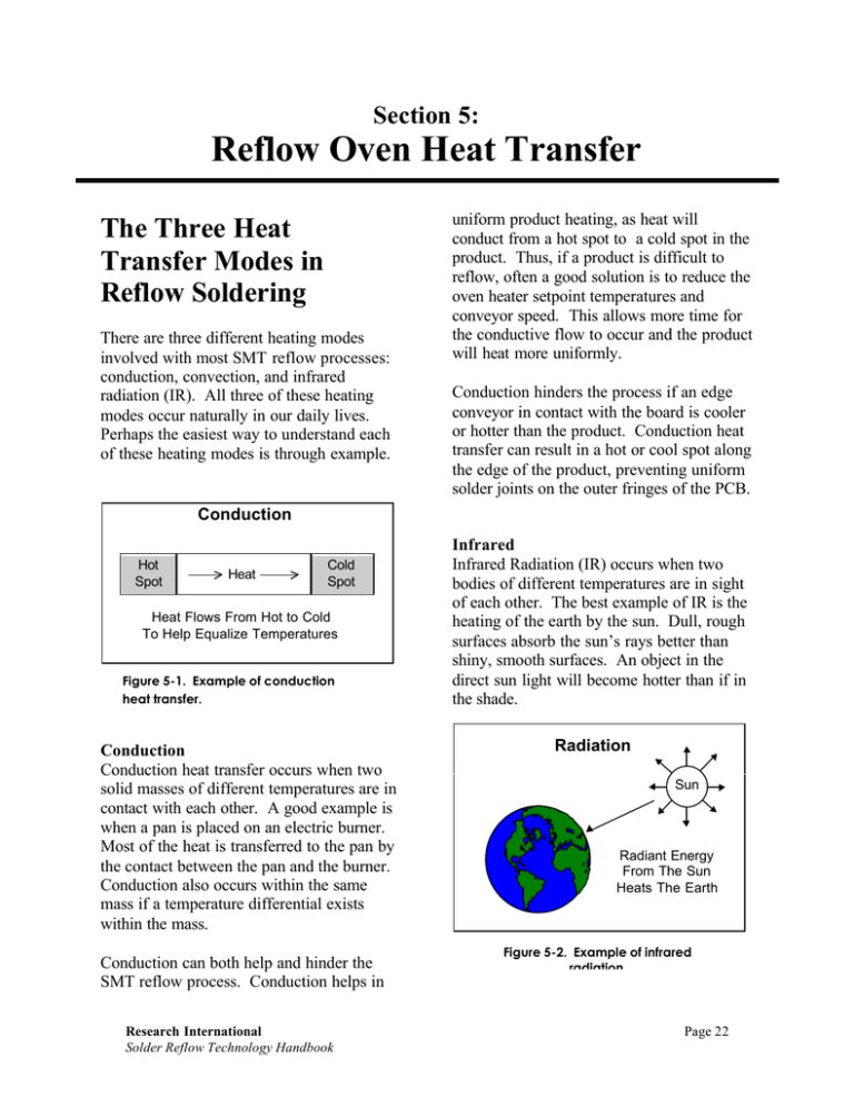
Section 5: Reflow Oven Heat Transfer The Three Heat Transfer Modes in Reflow Soldering There are three different heating modes involved with most SMT reflow processes: conduction, convection, and infrared radiation (IR). All three of these heating modes occur naturally in our daily lives. Perhaps the easiest way to understand each of these heating modes is through example. uniform product heating, as heat will conduct from a hot spot to a cold spot in the product. Thus, if a product is difficult to reflow, often a good solution is to reduce the oven heater setpoint temperatures and conveyor speed. This allows more time for the conductive flow to occur and the product will heat more uniformly. Conduction hinders the process if an edge conveyor in contact with the board is cooler or hotter than the product. Conduction heat transfer can result in a hot or cool spot along the edge of the product, preventing uniform solder joints on the outer fringes of the PCB. Conduction Hot Spot Heat Flow Cold Spot Heat Flows From Hot to Cold To Help Equalize Temperatures Figure 5-1. Example of conduction heat transfer. Conduction Conduction heat transfer occurs when two solid masses of different temperatures are in contact with each other. A good example is when a pan is placed on an electric burner. Most of the heat is transferred to the pan by the contact between the pan and the burner. Conduction also occurs within the same mass if a temperature differential exists within the mass. Conduction can both help and hinder the SMT reflow process. Conduction helps in Research International Solder Reflow Technology Handbook Infrared Infrared Radiation (IR) occurs when two bodies of different temperatures are in sight of each other. The best example of IR is the heating of the earth by the sun. Dull, rough surfaces absorb the sun’s rays better than shiny, smooth surfaces. An object in the direct sun light will become hotter than if in the shade. Radiation Sun Radiant Energy From The Sun Heats The Earth Figure 5-2. Example of infrared radiation. Page 22 IR in SMT applications works similarly. Fluxes, plastic components, and epoxy glass laminate absorb IR very well. Shiny, reflowed solder will reflect the IR energy away. Solder joints around small packages (such as chip resistors, capacitors, and SOIC’s) are in sight of the IR energy and heat very well. Solder joints around larger devices (such as PLCC’s) are shaded, and do not heat as well. Convection Convection heat transfer occurs when a fluid (such as air, nitrogen, or water) passes over an object (such as an SMT assembly). A cool breeze on a hot sunny day provides convective cooling. Hot air from a hair dryer provides convective heating. Convection heating or cooling requires contact of the flow with the solid part. Only the layer of the flow that is in contact with the part is actually transferring heat. Convection may be classified as natural or forced. Natural convection occurs when no flow is being forced over the object. Temperature differences between the object and the environment create the convective heat transfer. Perhaps the best example is the chimney effect, where a strong convective current rises away from the hot embers to the cooler outdoors. Forced convection requires an external force that pushes or pulls the flow over the object. A common house fan is a good example. Convection Hot Air Flow Cold Object Is Heated By Convection From The Hot Air Flow Figure 5-3. Example of convection heat transfer. Typically, forced convection heating or cooling rates are higher than natural convection rates. Most reflow ovens today use forced convection as the primary heat transfer mode. Research International won the 1998 SMT Magazine Vision Award for advances in Soldering Equipment. Notes: Page 23 Research International Solder Reflow Technology Handbook Heat Transfer Equations Conduction In order to understand what parameters are important in conduction heat transfer, one can consider the variables in the general conduction heat transfer equation. Q = K * A * ( T1 - T2 ) / ∆X Where: Q = Conduction heat transfer (W ) A = Cross sectional area (cm2 ) K = Thermal conductivity (W/cm -°C) T 1 = Temperature at point 1 (°C) T 2 = Temperature at point 2 (°C) ∆X = Thickness of material between points 1 and 2 (cm) The thermal conductivity (K) is a measure of how well the object conducts heat. Insulators (such as epoxy glass) have very low thermal conductivity and permit very low amounts of conductive heat transfer. Conductors (such as copper) have a very high thermal conductivity and permit high amounts of conductive heat transfer. Thus, an SMT assembly with high amounts of copper will heat more uniformly than one without much copper. Conduction through the circuit board during the reflow process improves heating uniformity, as the heat conducts from the hot spots to the cold spots. k = Thermal Conductivity t 1 Surface 1 Surface 2 t Conductive heat transfer is proportional to the cross sectional area (A) between point 1 and point 2. In SMT reflow, a thicker board will provide greater populated uniformity than a thin board since the cross sectional area is greater. Conductive heat transfer is also dependent upon the distance between point 1 and point 2 (∆X). The greater the distance, the less the heat transfer. Thus, a thicker board has a better chance of maintaining a higher temperature difference between the top and bottom side of the board than a thin board. IR - Infrared Infrared (IR) heat transfer occurs when two objects at different temperatures are in sight of each other. The heat is transferred by electromagnetic waves of 0.78 to 1000 micron wavelengths. All objects emit some level of infrared energy. The quantity of infrared energy emitted and the wavelength of the emission are both dependent upon the absolute temperature of the object. As the source temperature increases, the heat transfer output increases exponentially to the fourth power. Increasing the source temperature results in shorter wavelengths. Decreasing the source temperature results in longer wavelengths. In order to understand what parameters are important in infrared heating, one can consider the general equation for heat transfer between the heat source and the object being heated. The purpose is not to memorize the equation, but rather to point out the significance of what is involved. 2 ∆ x Figure 5-4. Conduction heat transfer model. Research International Solder Reflow Technology Handbook Page 24 The general equation for infrared heat transfer is: Q/A = Fv * ε s * αt ∗ σ * ( Ts4 - Tt 4 ) Where: Q/A = Fv = εs = αt = σ = Ts Tt Infrared heat transfer (W/cm2) Geometric view factor (0 - 1) Emmissivity of the source (0 - 1) Absorptivity of the target (0 - 1) Stefan-Boltzmann Constant (5.67 x 10⁻¹² W/cm2/°K 4) = Source temperature (°K) = Target temperature (°K) IR Source Control of infrared is generally done by controlling the source temperature. Providing that the overall source emission can be regulated, IR energy provides high levels of repeatability. Convection Convection heat transfer occurs when a fluid at a given temperature contacts a solid mass at a different temperature. If the fluid is hotter than the mass, the mass will be heated. If the fluid is cooler than the mass, the mass will be cooled. Perhaps the easiest way to understand convection is to look at the convection equation and note the significance of each variable. The following is the general equation for convection heating or cooling: This Area is Shaded by Adjacent Components Resulting in a Lower View Factor Figure 5-5. IR view factor. The geometric view factor Fv is the fraction of energy that leaves the source that hits the target. In SMT reflow, the oven chamber designs yield very high view factors in the range of 0.90 to 0.95. An important aspect of the view factor comes in product design. If two very large components are in close proximity to each other, the view factor to a solder joint between them is decreased, which makes it more difficult to reflow. The source emissivity (ε s ) and the target absorptivity factors (α t ) are in the range of 0.90 to 0.95 for most SMT applications. Solder paste is an excellent absorber of infrared energy. Shiny gold components may be difficult to heat, as they tend to be reflective. Most often, however, the board material, solder paste, and the components all absorb quite well. Page 25 Q/A = H * (Ta - Tt ) Where: Q/A = Convection heat transfer per unit area (W/cm2) H = Convective film coefficient (W/cm2-°C) T a = Fluid temperature (°C) T t = Target temperature (°C) The amount of heat transfer can be modified by either changing the convective coefficient (H) or the temperature difference (Ta - Tt ). Increasing the fluid temperature will increase the temperature difference, and thus the amount of heat transfer will increase proportionally. The convective coefficient (H) can have a significant impact on the heat transfer. The value of H is related to a number of variables, including velocity of the flow and angle of attack of the flow. Increasing the flow velocity will increase the value of H. For example, when one is outside in the wind, a low velocity cool breeze on a warm day will feel quite nice. However, a strong wind on that same day may feel very cold. Research International Solder Reflow Technology Handbook That is because the higher velocity wind has a higher convective coefficient, and thus removes heat more effectively from your skin. In SMT reflow applications, increasing the velocity of the flow also improves the amount of convection heat transfer. There are practical limits to this, as too high velocity may cause components to shift around. Parallel Flow Air Velocity (V) At Surface, V=0 Boundary Layer Thickness Perpendicular Flow Surface Agitation Prevents Boundary Layer Buildup Air Velocity (V) Figure 5-6. Fluid flow patterns. The flow direction also has a significant impact on H. Convection heat transfer relies on contact between the flow and the object. Parallel flow can result in a stagnation or boundary layer in which the heat transfer is diminished. Perpendicular flow can break up formation of a boundary layer and enhance the convective heat transfer. Perpendicular flow thus provides higher heat transfer rates than parallel flow. Research International Solder Reflow Technology Handbook Heat Transfer Mode Interaction and their Effect on SMT Reflow In SMT reflow applications, there is no such thing as pure convection or pure IR. The only way to achieve a 100% convection system would be to have gas flowing over the product with no chamber walls inside the reflow oven. Obviously the reflow oven is a mechanical device with walls that absorb or emit heat, so 100% convection is a physical impossbility. To have a 100% IR reflow system, the chamber would need to be operated in a vacuum (no air fluid heat transfer). Most reflow processes currently occur in some process gas whether air, nitrogen or vapor phase techniques. However, reflow oven heat transfer designs utilize a greater convection component, while others utilize IR as the primary heat source. For the sake of simplicity, this text will refer to a convection dominate heat transfer machine as a convection machine, and an IR dominated machine as an IR machine. In SMT reflow applications (with the exception of vapor phase), convection, conduction, and IR all play a role in the heating process. Referring to a system as 100% convection or 100% IR is an error in terminology. An oven may be dominated by convection or IR, but the other heat transfer is always present. IR dominant systems usually range in the convection/IR ratio of 60/40 to 40/60. Convection dominant systems have ratios in the range of 70/30 to 90/10. Page 26


