Prof_Elias_Inorg_lec_2
advertisement

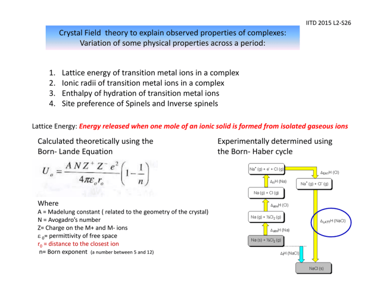
IITD 2015 L2‐S26 Crystal Field theory to explain observed properties of complexes: Variation of some physical properties across a period: 1. 2. 3. 4. Lattice energy of transition metal ions in a complex Ionic radii of transition metal ions in a complex Enthalpy of hydration of transition metal ions Site preference of Spinels and Inverse spinels Lattice Energy: Energy released when one mole of an ionic solid is formed from isolated gaseous ions Calculated theoretically using the Born‐ Lande Equation Where A = Madelung constant ( related to the geometry of the crystal) N = Avogadro’s number Z= Charge on the M+ and M‐ ions ε 0= permittivity of free space r0 = distance to the closest ion n= Born exponent (a number between 5 and 12) Experimentally determined using the Born‐ Haber cycle IITD 2015 L2‐S28 Lattice Energies (1st Row Divalent Transition Metal Halides and Main group halides) Compound Lattice energy (KJ/mol) Differences Measured Calculated (KJ/mol) NaCl ‐764 ‐764 0 MgF2 ‐2908 ‐2915 +7 MnF2 ‐2770 ‐2746 +24 FeF2 ‐2912 ‐2752 ‐160 CuF2 ‐3042 ‐2885 ‐157 NiF2 ‐3046 ‐2917 ‐129 The discrepancy for a six‐ coordinate transition metal ion can be explained by CFSE IITD 2015 L2‐S27 •According to the Born –Lande Equation one can expect a smooth increase in lattice energies as we go from left to right due to decrease in ionic radius of the metal ions •As anticipated a smooth curve is not seen: instead a double hump shaped curve is obtained •Ca2+ (d0), Mn2+(d5 HS) and Zn2+ (d10) which in common have CFSE =0 lie almost on the expected line. •Ions such as V2+ which show high CFSE in a weak field situation with high lattice energy values show significant deviation from the calculated lattice energies IITD 2015 L2‐S29 Ionic radii of transition metal ions in the presence of weak field and strong field ligands One can expect decrease the ionic radii of the M 2+ ions smoothly from Ca2+ to Zn 2+ due to the increase in nuclear charge But the plot shown below (left) for weak field ligands indicate that the expected regular decrease is absent expect for Ca2+, Mn 2+ and Zn 2+ For strong field ligands like CN‐ a different trend in variation is observed with a steady decrease till d6 (t2g6) +2 Oxidation state +3 Oxidation state IITD 2015 L2‐S30 Ionic radii of transition metal ions in the presence of weak field and strong field ligands Why does the ionic radii decreases and then increases?? Ti2+ (d2) electron occupy only t2g V2+ (d3) electrons occupy only t2g Cr2+ (d4HS) electrons start occupying the eg orbitals As the eg orbitals point directly towards the ligands, the repulsion between the metal electrons and ligand electrons will be higher than normal leading to the eventual increase in the ionic radius. In the case of strong field ligand such as cyanide there will be a steady decrease in ionic radii till t2g6 is reached. The same tend is observed also for M3+ transition metal complexes IITD 2015 L2‐S31 Variation of some physical properties across a period Enthalpy of hydration of transition metal ions It is the heat exchange involved when 1 mole of gaseous ions become hydrated M(g)2+ + excess H2O [M(H2O)6]2+ The amount of energy released when a mole of the ion dissolves in a large amount of water forming an infinite dilute solution in the process. Higher the charge on the ions and smaller the size, more exothermic will be the hydration energy. So it is expected to increase smoothly on going from left to right of the transition metals (green line in the graph) The heats of hydration show two “humps” consistent with the expected CFSE for the metal ions. The values for d5 and d10 are the same as expected with a CFSE equal to 0. IITD 2015 L2‐S32 Site preference of Spinels and Inverse Spinels Spinels are a class of crystalline solids of the general formula AB2O4 (AIIB III2O4 ) where A = main group (Group IIA) or transition metal ion in the +2 oxidation state B= main group (Group IIIA) or transition metal ion in the +3 oxidation state The weak field oxide ions provide a cubic close‐ packed lattice. In one unit cell of AB2O4 there are 8 tetrahedral and 4 octahedral holes Normal Spinel: A2+ Inverse Spinel: The +2 ions occupy 1/8th of the Td holes B3+ ions occupy ½ of the octahedral holes ion and one of the +3 ions exchange positions i.e. Td holes: +3 , Oh holes: both +2 and +3 ions Eg. MgAl2O4 Mg2+ Tetrahedral Al3+ octahedral Eg. Fe3O4 (Magnetite) Fe3+ Tetrahedral Fe 2+, Fe3+ octahedral IITD 2015 L2‐S33 If A and B of AB2O4 are both s or p block elements (e.g. MgAl2O4) it always show Spinel structure Question: Why does some AB2O4 compounds having transition elements as A and /or B prefer the inverse Spinel structure and some others normal Spinel structure? ANS: Crystal Field Stabilization Energy in an octahedral site [Also given as Octahedral site stabilization energy (OSSE) in some books] Mn3O4 = MnIIMnIII2O4 O2‐ = a weak field ligand Mn2+ = d5 HS : CFSE = 0 Mn3+ = d4 HS : CFSE = ‐0.6 Δo Mn2+ by exchanging positions with Mn3+ in an octahedral hole is not going to gain any extra crystal field stabilization energy. While Mn3+ by being in the octahedral hole will have CFSE. Therefore Mn3O4 will be Normal Spinel Fe3O4 = FeIIFeIII2O4 Fe2+ = d6 HS : CFSE =-0.4 Δo Fe3+ = d5 HS: CFSE = 0 Fe2+ by exchanging positions with Fe3+ to an octahedral hole is going to gain extra crystal field stabilization energy. While Fe3+ by being in the octahedral hole will not have any CFSE. Therefore Fe3O4 will be Inverse Spinel IITD 2015 L2‐S34 Magnetic properties of transition metal complexes Magnet off Magnet on: diamagnetic Magnet on: Paramagnetic Gouy balance to measure the magnetic susceptibilities 9 IITD 2015 L2‐S35 Magnetic properties of metal complexes Magnetism is caused by moving charged electrical particles (Faraday, 1830s). These particles can be the current of electrons through an electric wire, or the movement of charged particles (protons and electrons) within an atom. These charged particles move much like planets in a solar system: nucleus spin around its own axis, causing a very weak magnetic field. electrons orbit around the nucleus, causing a weak magnetic field. electrons spin around their own axis, causing a significant magnetic field . Spinning electrons generate the bulk of the magnetism in an atom. Within each orbit, electrons with opposite spins pair together, resulting in no net magnetic field. Therefore only unpaired electrons lead to magnetic moment The spin‐only formula (μs) μs = n(n + 2) IITD 2015 L2‐S36 Magnetic properties: Spin only and effective The spin‐only formula (μs) applies reasonably well to metal ions from the first row of transition metals: (units = μB,, Bohr‐magnetons) Metal ion dn configuration Ca2+, Sc3+ d0 Ti3+ d1 V3+ d2 V2+, Cr3+ d3 Cr2+, Mn3+ d4 d5 Mn2+, Fe3+ Fe2+, Co3+ d6 d7 Co2+ Ni2+ d8 Cu2+ d9 d10 Zn2+, Ga3+ μs(calculated) 0 1.73 2.83 3.87 4.90 5.92 4.90 3.87 2.83 1.73 0 μeff (observed) 0 1.7‐1.8 2.8‐3.1 3.7‐3.9 4.8‐4.9 5.7‐6.0 5.0‐5.6 4.3‐5.2 2.9‐3.9 1.9‐2.1 0 IITD 2015 L2‐S37 Spin and orbital contributions to μeff For the first‐row d‐block metal ions the main contribution to magnetic susceptibility is from electron spin. However, there is also an orbital contribution (especially for the second and third row TM) from the motion of unpaired electrons from one d‐orbital to another. This motion constitutes an electric current, and so creates a magnetic field. d‐orbitals spinning electrons spin contribution – electrons are orbital contribution ‐ electrons spinning creating an electric move from one orbital to current and hence a magnetic field another creating a current and hence a magnetic field Crystal Field theory explains magnetic moments of TM complexes IITD 2015 L2‐S38 Strength of the ligand, type of complex , size of the metal and its oxidation state affects crystal field splitting IITD 2015 L2‐S39 Temperature dependence of magnetic moments Fe(Phen)2(NCS)2 How crystal field theory explains temperature dependence of μeff Fe2+ = d6 Ferromagnetism: IITD 2015 L2‐S40 In a normal paramagnetic material, the atoms containing the unpaired electrons are magnetically dilute, and so the unpaired electrons in one atom are not aligned with those in other atoms. In ferromagnetic materials, such as metallic iron, or iron oxides [magnetite (Fe3O4)], where the paramagnetic iron atoms are very close together, they can create an internal magnetic field strong enough that all the centers remain aligned: unpaired electrons oriented randomly unpaired electrons unpaired electrons aligned in their own common magnetic field a) paramagnetic, magnetically dilute in e.g. [Fe(H2O)6]Cl2. Fe atoms separated by diamagnetic atoms a) b) ferromagnetic, as in metallic Fe or some Fe oxides. b) IITD 2015 L2‐S41 Antiferromagnetism: electron spins in opposite directions in alternate metal atoms Here the spins on the unpaired electrons become aligned in opposite directions so that the μeff approaches zero, in contrast to ferromagnetism, where μeff becomes very large. An example of anti‐ ferromagnetism is found in MnO and oxymyloglobin. antiferromagnetism Observed in Oxyhemoglobin and oxymyoglobin Which is the strongest ferromagnetic material in the world? NEODYMIUM MAGNET Nd2Fe14B IITD 2015 L2‐S42 Problem solving !! Cobalt form three octahedral complexes, [MCl6]4‐, [M(R2NCS2)3] and [M(CN)5(H2O)]3‐. These have magnetic moments 0, 1.73 and 3.9 BM (not in the order). Assign the moments to the complexes and predict the relative strength of the dithiocarbamate ligand. Solution [CoCl6]4‐ Co2+, 3d 7 ,Cl‐ weak ligand, HS, 3 unpaired e’s ~ 3.9 BM [Co(CN)5(H2O)]3‐. Co2+, CN‐ strong ligand, LS 1 unpaired e 1.73 BM [Co(R2NCS2)3], Co3+, 3d 6 , 0 BM means ligand is strong field and low spin complex IITD 2015 L2‐S43 Distortion of some octahedral complexes All six Ni‐O bonds equal at 2.05 Å [Ni(H2O)6]2+ no distortion two long axial Cu‐O bonds = 2.45 Å four short in‐plane Cu‐O bonds = 2.00 Å [Cu(H2O)6]2+ distortion lengthens axial Cu‐O’s IITD 2015 L2‐S44 Orbital Degeneracy versus Electronic Degeneracy Energy Orbital degeneracy: The 5 d orbitals are of the same energy in spherical field. This orbital degeneracy is lifted (reduced) in an octahedral field (to t2g and eg ) Electronic Degeneracy : Case of t2g1 Here there are three different ways by which the single electron can occupy the t2g orbitals. There are three possible electronic configurations which are of the same energy. Electronic degeneracy is present eg t2g eg t2g 5 d orbitals in a spherical field Electronic Degeneracy : Case of t2g3 Here there is only one way by which the three electron can occupy the t2g orbitals. So there is no electronic degeneracy eg eg t2g t2g


