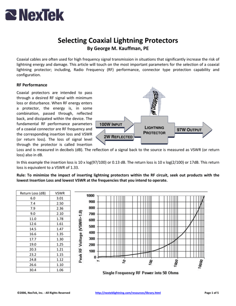
Selecting Coaxial Lightning Protectors
By George M. Kauffman, PE
Coaxial cables are often used for high frequency signal transmission in situations that significantly increase the risk of
lightning energy and damage. This article will touch on the most important parameters for the selection of a coaxial
lightning protector; including, Radio Frequency (RF) performance, connector type protection capability and
configuration.
RF Performance
Coaxial protectors are intended to pass
through a desired RF signal with minimum
loss or disturbance. When RF energy enters
a protector, the energy is, in some
combination, passed through, reflected
back, and dissipated within the device. The
fundamental RF performance parameters
100W INPUT
LIGHTNING
of a coaxial connector are RF frequency and
97W OUTPUT
P
ROTECTOR
the corresponding insertion loss and VSWR
2W REFLECTED
(or return loss). The loss of signal level
through the protector is called Insertion
Loss and is measured in decibels (dB). The reflection of a signal back to the source is measured as VSWR (or return
loss) also in dB.
In this example the insertion loss is 10 x log(97/100) or 0.13 dB. The return loss is 10 x log(2/100) or 17dB. This return
loss is equivalent to a VSWR of 1.33.
Rule: To minimize the impact of inserting lightning protectors within the RF circuit, seek out products with the
lowest Insertion Loss and lowest VSWR at the frequencies that you intend to operate.
Return Loss (dB)
6.0
7.4
7.9
9.0
11.0
12.6
14.5
16.6
17.7
19.0
20.3
23.2
24.8
26.6
30.4
VSWR
3.01
2.50
2.36
2.10
1.78
1.61
1.47
1.35
1.30
1.25
1.21
1.15
1.12
1.10
1.06
©2006, NexTek, Inc. - All Rights Reserved
http://nexteklightning.com/resources/library.html
Page 1 of 5
The RF power of a circuit produces a voltage on the center conductor. In most cases the system impedance is 50Ω, so
the relationship between power and voltage can be expressed as the familiar W = V2/50 Ω. The actual voltage is
increased by the VSWR value of the entire system, including the antenna and the end termination.
In cases of multiple simultaneous transmission bands it is necessary to calculate the voltage for each RF frequency
separately and sum.
RF Power
W
dBm
0.0001
0.001
0.01
0.1
1
2
5
10
20
50
100
200
500
1000
-10.00
0.00
10.0
20.0
30.0
33.0
37.0
40.0
43.0
47.0
50.0
53.0
57.0
60.0
RF Voltage
(50 Ω VSWR=1.0)
Vrms
Vpeak
0.071
0.224
0.71
2.24
7.07
10.0
15.8
22.4
31.6
50.0
70.7
100.0
158.1
223.6
0.10
0.32
1.00
3.16
10.0
14.1
22.4
31.6
44.7
70.7
100
141
224
316
Some applications require multiple simultaneous transmission and
receiving. For most telecom applications, specifying the InterModular Interference (IMI) or Passive Inter-Mod (PIM) interference is
typically required. PIM is usually specified in dB, similar to return
loss. More traditional electrical parameters (volts and amperes) are
required if dc power is required, particularly if the coaxial cable
carries power for far end equipment in addition to the RF signals.
Connector Types
The connector types most commonly used for communication
systems include the N, 7-16 DIN, TNC and the SMA connector. In
addition, the 75 Ohm F connector is popular in video/cable
applications. Each connector brings a specific geometry of both the
inner conductor and outer conductor; in most connectors the outer
conductor has a significantly greater current capacity than the center
pin. This is beneficial because the outer shield is usually connected to
the grounding system and can take a substantial portion of the lightning current. In addition, the transient current
capacity limitation of the center pin should also be considered. The current rating of most center pins is rated as the
survivability of ten 8x20µs ampere pulses, shown in Table X below.
Connector
Pin Diameter
Quality
Transient
Capacity in kA
Connector type
7-16 DIN
UHF
N
TNC
BNC
SMA
F(75)
0.276”/7mm 0.19”/4.8mm 0.12”/3.1 0.08”/2.1mm 0.05”/1.3mm ~.04”/1mm
Higher
100kA
50kA
30kA
20kA
20kA
5kA
15kA
Lower
50kA
10kA
10kA
5kA
5kA
2.5kA
3kA
Table X.
Larger connector pin formats have a longer lifetime rating. The largest differentiator between high and low quality
protectors is the female contact material and finish. The female contacts for smaller format connectors, particularly
of N, TNC or BNC and SMA configurations, must be a hardened copper alloy for maximum pulse lifetime. Low quality
protectors use soft bronze or even softer brass female sockets, which can easily be bent or loosened during assembly
or mating, and are further weakened with the heating caused by high lightning currents. You can confirm your pin
material this with a simple test: Find a paper clip, or pin, that will just fit into the connector socket. Insert the pin into
the female socket and angle the pin about 20o-30o from the pin centerline to bend open a socket spring finger.
Return the pin to the center and withdraw the pin from the socket. If spring finger of the pin returns to its original
position, you have a high quality contact. Under severe bending, a high quality pin will break off, as opposed to
staying bent. If the spring finger stays bent, do not use this female connector type (whether on the protector or on
the attached cable). NexTek uses specialized contacts for long pulse lifetime including hardened copper alloy pins
©2006, NexTek, Inc. - All Rights Reserved
http://nexteklightning.com/resources/library.html
Page 2 of 5
with gold finish for female contact in all N and TNC/BNC and SMA protectors. Other techniques are used to extend
the life of 7-16 and UHF female contacts.
Each connector type has inherent
maximum voltage, current, and RF
power limitations. Be sure to
select a connector that is
compatible with the radio
manufacturers’ recommendations,
particularly for higher RF power
applications.
Protection Capability and Performance
The protection capability and performance includes the maximum transient capability of the protectors and the
ability to reduce high voltages to safer and acceptable levels. The protection capability of a protector is usually rated
in its ability to guard against or survive 8x20µs lightning current pulses.
Gas Discharge Tube (GDT) Protectors
If the signal is less than 400 MHz, or the protector must pass dc, most protectors rely on a Gas Discharge Tube (GDT)
which triggers when a large voltage appears and shorts out the remaining transient. GDTs are a reliable, long life
workhorse of the industry and have the highest transient current capability for their size of any similar protection
component. The transmission peak RF voltage should be less than 60% of the GDT voltage rating, otherwise the GDT
may react to the normal RF voltage levels. Also, since the GDT voltage is rated higher than the normal RF voltage and
the GDT takes some time to respond, a very short pulse associated with these two factors will occur on the protected
line.
The current capacity of industry standard GDT’s range from a lifetime of ten 20kA pulses to lower values of 5kA
pulses. While GDTs usually have a very long lifetime, UHF and especially 7-16 type connectors will easily outlast even
the highest quality GDT. Therefore, protectors using these connector types should allow for a replaceable GDT and
periodic replacement. Protectors using SMA, F, or BNC connectors typically do not benefit from a replaceable GDT;
because when the GDT requires replacement, most likely the center pin has also been damaged.
If the more rugged N and sometimes the TNC connectors are protected from direct strikes, a high quality GDT has a
very long life expectancy. However, in high risk areas the GDT might degrade. The GDT lifetime can be managed in
three ways:
a. replacing the entire protector periodically or upon equipment damage,
b. use of redundant protectors on the line, so that when the first protector and connector or wire is damaged, the
second protector will continue to protect, or
c. replacing the GDT component.
If you periodically replace a GDT or the whole protector, remember the cable or connector is not being renewed, and
requires inspection if poor transmission is observed.
The best way to reduce long term expenses and ensure high availability service for TNC and especially N or 7-16
connectors is to require a minimum 20kA (10 8x20µs pulses) lifetime, or 50kA one pulse rated protectors. There is no
reason to accept a shorter life protector such as 5kA or 10kA, unless very high frequency operation or a smaller
format connector is required.
©2006, NexTek, Inc. - All Rights Reserved
http://nexteklightning.com/resources/library.html
Page 3 of 5
Shorted Conductor Protectors
If the signal is over 400 MHz to over 6GHz and there is no dc present in the application, the protector of choice is
either a quarter wave stub or inductor shorting design. Called pass band devices, these protectors use a high current
capacity shunt from the center conductor to the outer conductor. These protectors exhibit remarkable RF
performance, especially above 3 GHz.
Since there is no voltage sensitive component used in the protection scheme, the RF power capability of a quarterwave stub protector is usually coordinated with the RF connector. In addition, the shunt current capacity can be
matched to the connector pin type, so that longer lifetime protectors are the norm for larger connector size quarter
wave protectors. DIN 7-16 protectors can have ratings of 100kA or more. N protectors can have ratings of 60kA.
Finally, since there is no turn-on delay similar to a GDT, there is a much more limited voltage overshoot upon
operation. Quarter wave stub protectors have a long lifetime and provide exceptional transient current capacity with
excellent protection.
Let-Through
The ability to protect is usually evaluated by injecting a standard impulse and measuring what passes through the
protector. The most common input is a 1.2x50µs voltage waveform with an 8x20s current waveform. The 1.2x50 is
defined, as in the current waveform, as rise time of 1.2µs and pulse width of 50s. The most common term is “letthrough” and is usually stated in peak voltage and energy. With an input of 6kV/3kA the let-through for GDT based
protectors is about 600Vpeak and 300µJ. The GDT typically triggers in 100ns. A quarter wave stub based protector
has a typical let-through of 15V and 10µJ.
Some protectors use additional components, such as dc blocks, which can reduce let-through, but at the sacrifice of
bi-directional protection. Bi-directional means that the transient can enter the protector from either side. In real
applications, transients can occur from the ac power mains, the coaxial cable or other metal members or conductors.
It is usually important that a protector can protect a transient entry from either side. In addition, unidirectional
protectors can inadvertently be installed “backwards”, resulting in virtually no protection. Also, the input stage of
most transceivers have band pass filtering which can provide this same energy limiting action that works very well in
the majority of applications
Most coaxial protectors use GDT or quarter wave (sometimes called inductor) technology as the fundamental
protection element. Further refinements are available, including designs to overcome GDT lifetime or response delay,
and other enhancements to significantly reduce let-through energy in both GDT and quarter wave stub protectors.
For example, NexTek NEMP Fine Protectors can dramatically reduce let-through energy and response time.
©2006, NexTek, Inc. - All Rights Reserved
http://nexteklightning.com/resources/library.html
Page 4 of 5
Configuration, Mounting and Grounding
The configuration of the protector can be used to make it easier to mount, connect and ground successfully. The
figure below provides some general guidance on how to mount and ground a variety of protector styles. If the
application is outdoors, waterproof units are required. Remember that grounding a protector is essential to ensure
protection of susceptible equipment.
Conclusion
When selecting your coaxial protector use the following criteria.
1. Lowest insertion loss and VSWR for the frequency
2. Largest recommended connector type
3. Maximum Transient Capacity
4. Best Bi-directional Protection Level
5. Most convenient mounting and grounding
©2006, NexTek, Inc. - All Rights Reserved
http://nexteklightning.com/resources/library.html
Page 5 of 5


