3/2.1/B/2
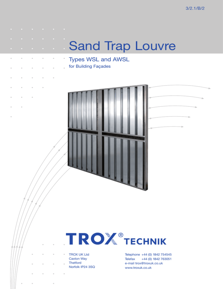
Sand Trap Louvre
Types WSL and AWSL
for Building Façades
TROX UK Ltd
Caxton Way
Thetford
Norfolk IP24 3SQ
Telephone +44 (0) 1842 754545
Telefax
+44 (0) 1842 763051
e-mail trox@troxuk.co.uk
www.troxuk.co.uk
Contents · Description · Materials · Fixing
Description · Materials · Fixing ______________________ 2
Construction · Dimensions · Selection Example _______ 3
Technical Data · Order Details _______________________ 4
Description
Materials
The sand trap louvre is used as pre-filter for the protection
of air conditioning plants in areas exposed to extreme
levels of industrial pollution. It has a degree of separation
of sand and large dust particles, even in cases of high dust
concentrations. The vertically arranged sections and holes for
sand drainage ensure the sand trap louvre is self cleaning and
maintenance-free. The sand trap louvre is designed to separate
large particles at low air velocities, thus avoiding excessive dust
loading on conventional plant filters. It is not intended as a
substitute for conventional supply air filtration plant.
Basic construction either aluminium (AWSL) or galvanised steel
(WSL). Bird screen galvanized steel mesh 12 x 12 x 1 mm.
Standard finish AWSL mill, WSL galvanized or powder coated
RAL RAL 9010 25% gloss, other RAL colours and of gloss
finish on request. For all external application AWSL powder
coat finish to BS EN 12206-1;2004, WSL powder coat finish to
BS EN 13438:2005.
Louvre Fixing
Louvre rear section to be site drilled for fixings supplied by
others.
2
Construction · Dimensions
Dimensions
Standard Sizes · Single Section
Width B in mm
150
300
450
600
750
900
1050
1200
1350
1500
1650
1800
1949
Height H in mm
150
300
450
600
750
900
10501)
12001)
13501)
15001)
16501)
18001)
19491)
1)
All combinations for B and H dimensions can be supplied. For
sizes larger than indicated in the table several sections can be
combined to provide any combination of overall width or height.
Sand trap louvres with H between 1050 and 1949 integral sand
chutes are fitted (see detail 1), H between 1950 and 3900 they
are split on height and supplied with additional sand chute
(see detail 2), loose for fitting on site by others. The additional
support for reinforcement and assembly of the sand trap louvre
combination is to be supplied on site by others. Sand trap
louvres with B = 1950 to 3900 are also split into end section
left, end section right and middle if required. The vertical joint
between two end sections of sand trap louvre is capped on
site by others with a loose channel section supplied.
With Split blades and sand chute (see Detail 1)
Construction
Two rows of vertically arranged channels sections to form a
labyrinth for the air path. Base frame has drainage holes for the
sand ensuring the louvre is self cleaning and maintenance free.
Weight
Net weight without packing
Aluminium approx. 18 kg per m2 of area (B x H)
Steel approx. 27 kg per m2 of area (B x H)
Construction
Vertical section
Horizontal section B = 150...1949 mm
45
B
Detail 2
H = 1050...1949 mm
H = 1950...3900 mm
H
H-10
H + 100
Sand
chute
25 50
100
150
Detail 1
50
B - 10
50
76
Sand drain holes
B + 100
Additional support for
reinforcement by others
Horizontal section B = 1950...3900 mm
25
Note: Louvre supplied with
Bird Mesh Screen.
Galvanised mesh
12 x 12 x 1 mm
Supplied as separate sections –
assembly by others on site
Central channel supplied
loose to cap joint
End section left – EL
End section right – ER
3
Technical Data · Order Details
Pressure
drop in
Total pressure
in Pa
Pa
Pressure Drop
Filtration
The filtration performance is dependant on the dust type
and the velocity of the air:
Particle Size
Filtration Efficiency in %
Range
at 1.0 m/s
at 2.0 m/s
150
125
350-700
75-700
90
60
70
approx. 30
100
75
Example
For normal operation conditions the sand trap louvres
should be rated for a face velocity of approx 1.0 m/s.
50
25
0
0
0.5
1.0
1.5
2.0
2.5
Face velocity in m/s
(based on B x H areal)
2430 l/s (8750) m3/h
Volume flow
With a face velocity of 1.0 m/s
Area of louvre required
approx. 2.4 m2
Dimensions selected
– Assembly width
– Assembly height
1800 mm
1350 mm
Total pressure drop
approx. 30 Pa
Order Code
- WSL
Complete Louvre or
multi-section 1) 2)
M = middle section
EL = end left section
ER = end right section
/
900 x 900
/
Standard Sizes
BxH
0
/
0
/
P9
Not used
/
RAL 9010
/ 25% Gloss
Finish/colour
A1 = Aluminium mill finish
G0 = Pre Galvanised sheet
P9 = External use Powder coat finish to RAL colour
Subject to change · All rights reserved © TROX UK (01/2012)
RAL colours and levels of gloss finish on request
Type
AWSL - Aluminium sand trap louvre with galvanised steel bird screen.
WSL - Galvanised steel sand trap louvre with galvanised steel bird screen.
1)
2)
Split on H Dimension when H exceeds 1949 mm
Split on B Dimension when B exceeds 1949 mm
Specification Text
Sand trap louvres for the protection of air intakes exposed to
extreme levels of industrial / sand pollution. To separate
large dust particles / sand at low air velocities, To be self
cleaning and maintenance free. To be used as initial filter to
protect conventional plant filters from excessive dust
loading.
Order Example
Make: TROX
Type: AWSL / 1800x1350 / 0 / 0 / P9 / RAL 9010 / 25% Gloss
4


