®
Frost Fighter
Technical Bulletin
Bulletin 106
World leader in after market vehicle defroster solutions
ThermaSync Switch and Connection
There are four wires coming out of the ThermaSync Defroster
Control running to the defroster switch. This bulletin shows what the
ThermaSync switch wires do.
Proceed with caution
Modifying the switch wiring voids any and all warranty policies for the
ThermaSync control. Planned Products LLC is not responsible for any
consequence of this modification. It is possible to damage any device
connected to the ThermaSync control and/or the control.
What we do not know
We do not know the wire colors coming from existing defroster
switches or other devices as there is no standard in this area.
What works
The ThermaSync switch uses two light emitting diodes (LED) for the red
indicator light and a momentary normally open push button.
There are a few things to know in addition:
1. The ThermaSync driver for the LEDs is constant current at 7.6mA ,
with a voltage of 9.5 volts.
2. If connecting to a single LED it is important that the anode
be connected to the Black lead prior to applying power since
connecting the cathode to the Black lead will exceed the reverse
voltage specifications and likely destroy the LED.
3. Some switches have three leads and some have four but all must
be momentary normally open.
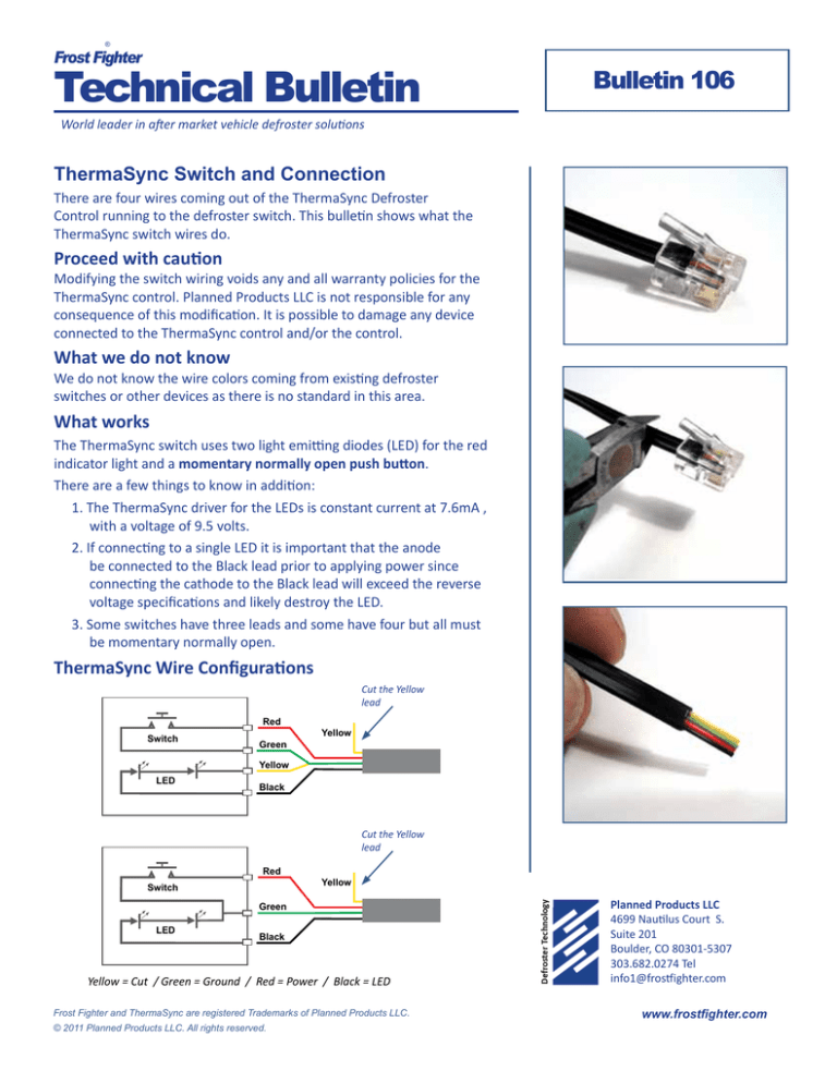
ThermaSync Wire Configurations
Cut the Yellow
lead
Red
Switch
Green
Yellow
Yellow
LED
Black
Cut the Yellow
lead
Red
Switch
Yellow
Green
LED
Black
Yellow = Cut / Green = Ground / Red = Power / Black = LED
Frost Fighter and ThermaSync are registered Trademarks of Planned Products LLC.
© 2011 Planned Products LLC. All rights reserved.
Planned Products LLC
4699 Nautilus Court S.
Suite 201
Boulder, CO 80301-5307
303.682.0274 Tel
info1@frostfighter.com
www.frostfighter.com


