Four bits Encoder with Dynamic Priority
advertisement
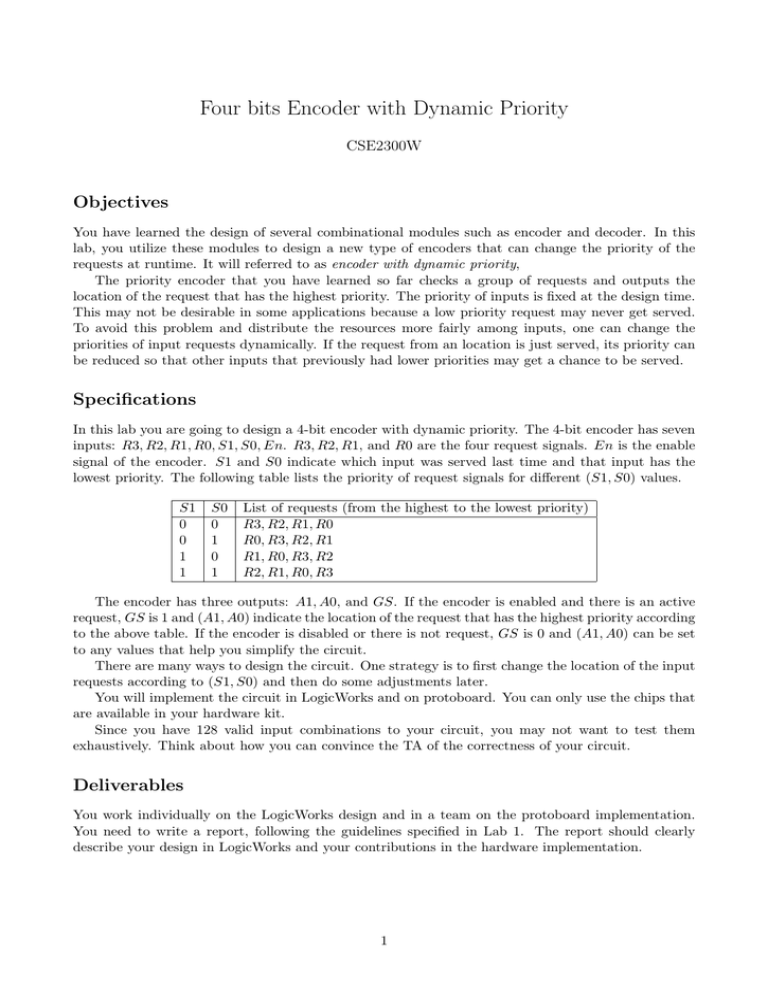
Four bits Encoder with Dynamic Priority CSE2300W Objectives You have learned the design of several combinational modules such as encoder and decoder. In this lab, you utilize these modules to design a new type of encoders that can change the priority of the requests at runtime. It will referred to as encoder with dynamic priority, The priority encoder that you have learned so far checks a group of requests and outputs the location of the request that has the highest priority. The priority of inputs is fixed at the design time. This may not be desirable in some applications because a low priority request may never get served. To avoid this problem and distribute the resources more fairly among inputs, one can change the priorities of input requests dynamically. If the request from an location is just served, its priority can be reduced so that other inputs that previously had lower priorities may get a chance to be served. Specifications In this lab you are going to design a 4-bit encoder with dynamic priority. The 4-bit encoder has seven inputs: R3, R2, R1, R0, S1, S0, En. R3, R2, R1, and R0 are the four request signals. En is the enable signal of the encoder. S1 and S0 indicate which input was served last time and that input has the lowest priority. The following table lists the priority of request signals for different (S1, S0) values. S1 0 0 1 1 S0 0 1 0 1 List of requests (from the highest to the lowest priority) R3, R2, R1, R0 R0, R3, R2, R1 R1, R0, R3, R2 R2, R1, R0, R3 The encoder has three outputs: A1, A0, and GS. If the encoder is enabled and there is an active request, GS is 1 and (A1, A0) indicate the location of the request that has the highest priority according to the above table. If the encoder is disabled or there is not request, GS is 0 and (A1, A0) can be set to any values that help you simplify the circuit. There are many ways to design the circuit. One strategy is to first change the location of the input requests according to (S1, S0) and then do some adjustments later. You will implement the circuit in LogicWorks and on protoboard. You can only use the chips that are available in your hardware kit. Since you have 128 valid input combinations to your circuit, you may not want to test them exhaustively. Think about how you can convince the TA of the correctness of your circuit. Deliverables You work individually on the LogicWorks design and in a team on the protoboard implementation. You need to write a report, following the guidelines specified in Lab 1. The report should clearly describe your design in LogicWorks and your contributions in the hardware implementation. 1

