OC-3/STM-1 Analysis Card
advertisement
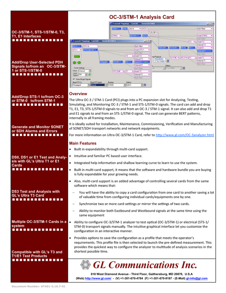
OC-3/STM-1 Analysis Card OC-3/STM-1, STS-1/STM-0, T3, T1, E1 Interfaces Add/Drop User-Selected PDH Signals to/from an OC-3/STM1 or STS-1/STM-0 Add/Drop STS-1 to/from OC-3 or STM-0 to/from STM-1 Generate and Monitor SONET or SDH Alarms and Errors Overview The Ultra OC-3 / STM-1 Card (PCI) plugs into a PC expansion slot for Analyzing, Testing, Simulating, and Monitoring OC-3 / STM-1 and STS-1/STM-0 signals. The card can add and drop T1, E1, T3, STS-1/STM-0 signals to and from an OC-3 / STM-1 signal. It can also add and drop T1 and E1 signals to and from an STS-1/STM-0 signal. The card can generate BERT patterns, internally in all framing modes. It is ideally suited for Installation, Maintenance, Commissioning, Verification and Manufacturing of SONET/SDH transport networks and network equipments. For more information on Ultra OC-3/STM-1 Card, refer to http://www.gl.com/OC-3analyzer.html Main Features Built in expandability through multi-card support. DS0, DS1 or E1 Test and Analy- Intuitive and familiar PC based user interface. sis with GL’s Ultra T1 or E1 Integrated help information and shallow learning curve to learn to use the system. Cards Built in multi-card support, it means that the software and hardware bundle you are buying is fully expandable for your growing needs. Also, multi-card support is an added advantage of controlling several cards from the same software which means that: DS3 Test and Analysis with GL’s Ultra T3 Card You will have the ability to copy a card configuration from one card to another saving a lot of valuable time from configuring individual cards/equipments one by one. Synchronize two or more card settings or mirror the settings of two cards. Ability to monitor both Eastbound and Westbound signals at the same time using the same equipment Multiple OC-3/STM-1 Cards in a Ability to configure OC-3/STM-1 analyzer to test optical (OC-3/STM-1) or electrical (STS-1/ system STM-0) transport signals manually. The intuitive graphical interface let you customize the configuration in an interactive manner. Compatible with GL’s T3 and T1/E1 Test Products Provides options to save the configuration as a profile that meets the operator's requirements. This profile file is then selected to launch the pre-defined measurement. This provides the quickest way to configure the analyzer to multitude of analysis scenarios in the shortest possible time. 818 West Diamond Avenue - Third Floor, Gaithersburg, MD 20878, U.S.A (Web) http://www.gl.com/ - (V) +1-301-670-4784 (F) +1-301-670-9187 - (E-Mail) gl-info@gl.com Document Number: UT401-3.10.7-01 Page 2 Benefits Cost Effective: Most cost effective and expandable solution for SONET/SDH testing. Comprehensive: The OC-3/STM-1 and STS-1/STM-0 receivers monitor SONET/SDH signals and present in real-time comprehensive diagnostics of SONET/SDH alarms, errors and pointer justifications. PC Based: Can convert any PC (Desktop, Lunchbox, or Laptop) to a SONET/SDH analysis, testing, simulating, and monitoring platform. This will maximize the returns from your current investment on desktop / laptop PCs. Complete Solution: In conjunction with GL’s Ultra T1 Card, Ultra E1 Card and Ultra T3 Card in the same PC, the Ultra OC3/STM-1 Card will provide a complete OC-3/STM-1, DS3, DS1, E1 and DS0 testing solution. Flexible: Use multiple OC-3/STM-1 cards in the same PC controlled by the same software, or distribute the cards in different PCs, thereby providing the most flexible solution for your unique testing needs. Bit Error Rate (BER) Test Modify the Framing and Pattern of the transmitted signal as well as set the receive side to listen to a specific payload and pattern. Ability to insert single BERT error (in T3, VC-3 and VC-4 signals) as well as insert errors at a predefined error rate (only in T3 signal) Supported Signal Mappings VC-4 (Bulk filled) --> AU-4 --> STM-1 STM-0 --> AU-3 --> STM-1 (Add/Drop) VC-3 (Bulk Filled) --> AU-3 --> STM-1 T3 --> AU-3 --> STM-1 (Internal and Add/Drop) Figure: BER Test Window T3 --> AU-3 --> STM-0 (Internal only) Error Insertion and Alarm Generation E1 --> TU-12 --> TUG-2 --> AU-3 --> STM-0 Allows you to insert various SDH and secondary signal errors as well as generate various alarms. Depending on the current card configuration, the sub-panels displayed will differ. If the card is looped back to itself (internally using the loopback option or externally using a cable) the alarms generated using this window will be detected on the Monitor Window E1 --> TU-12 --> TUG-2 --> AU-3 --> STM-1 E1 --> TU-12 --> TUG-2 --> TUG-3 --> AU-4 --> STM-1 T1 --> TU-11 --> TUG-2 --> AU-3 --> STM-0 T1 --> TU-11 --> TUG-2 --> AU-3 --> STM-1 T1 --> TU-11 --> TUG-2 --> TUG-3 --> AU-4 --> STM-1 T1 --> TU-12 --> TUG-2 --> AU-3 --> STM-0 T1 --> TU-12 --> TUG-2 --> AU-3 --> STM-1 T1 --> TU-12 --> TUG-2 --> TUG-3 --> AU-4 --> STM-1 Figure: Error Insertion and Alarm Generation Window Figure: SDH Signal Mappings 818 West Diamond Avenue - Third Floor, Gaithersburg, MD 20878, U.S.A (Web) http://www.gl.com/ - (V) +1-301-670-4784 (F) +1-301-670-9187 - (E-Mail) gl-info@gl.com Document Number: UT401-3.10.7-01 Page 3 Specifications Physical Interfaces OC-3/STM-1: SC Connector STS-1/STM-0/T3: Male BNC Connector T1/E1: RJ48c Connector External Clock: MCX Connector PC Interface: PCI 2.1 Compliant OC-3/STM-1 Line Interface Physical Interface: SC Connector Fiber Pigtail: Single mode, 1310 nm Pulse Mask: Meets ITU-T G.957 and Bellcore DR-253-CORE Line Code: NRZ Output Clock Reference: Recovered OC-3 Clock, External 19.44 MHz, or Internally Generated 155.52MHz ± 4.6ppm Rx Sensitivity: -31 dBm STS-1/STM-0 Line Interface Physical Interface: BNC Male Connectors Output Clock Reference: Recovered STS-1/STM-0 Clock, External 19.44 MHz, or Internally Generated 51.84MHz ± 4.6ppm T3 Line Interface Physical Interface: BNC Male Connectors Line Code Format: B3ZS Framing Format: M23, C-bit Input Frequency: 44.736 Mbps Receiver Interface: DSX-3 (Terminate or Monitor) Input Impedance: 75 Ohms Input Level: Terminate- 0.09 Vp – 0.85 Vp Monitor 0.025– 0.08 Vp (Up to 26 dB flat loss relative to nominal DSX) Output Level: DSX - Per TR-TSY-0004999, 0.75 to 0.85 Vp Output Clock Source: Recovered or Internal T1/E1 Line Interface Physical Interface: RJ48c Connector Line Code Format: AMI or B8ZS (T1), HDB3 (E1) Input Frequency: 1.544 Mbps (T1) or 2.048 Mbps (E1) Receiver Interface: Terminate Input Impedance: 100 Ohms (T1), 120 Ohms (E1) Input Level: +75 mV to 6.0 V base to peak or –30 dBsX to +6 dBsX +3.0 +/-0.2 Base to Peak Selectable 0 to 655 ft. Pulse Equalization Setting for T1 Short Haul, or line build outs for 0 dB to –22.5 dB (T1 Long Haul) Output Level: 818 West Diamond Avenue - Third Floor, Gaithersburg, MD 20878, U.S.A (Web) http://www.gl.com/ - (V) +1-301-670-4784 (F) +1-301-670-9187 - (E-Mail) gl-info@gl.com Document Number: UT401-3.10.7-01 Page 4 Specifications (continued) External Clock Interface Physical Interface: SC Connector Electrical Standard: RS485/RS422 SONET/SDH Framing Formats SONET: STS-3, STS-3c, STS-1 Output Clock Reference: SDH: STM-1 (AU-3, AU-4) Payload Mappings SONET STS-3c (Bulk Filled) àOC-3 STS-1 → OC-3 (Add/Drop) STS-1 (Bulk Filled) → STS-1 T3 → OC-3 (Internal and Add/Drop) T3 → STS-1 (Internal only) E1 → VT-2 → STS-1 (Internal and Add/Drop) E1 → VT-2 → OC-3 (Internal and Add/Drop) T1 → VT-1.5 → STS-1 (Internal and Add/Drop) T1 → VT-1.5 → OC-3 (Internal and Add/Drop) SDH Bulk filled) → AU-4 → STM-1 STM-0 → AU-3 → STM-1 (Add/Drop) VC-3 (Bulk Filled) → AU-3 → STM-1 T3 → AU-3 → STM-1 (Internal and Add/Drop) T3 → AU-3 → STM-0 (Internal only) E1 → TU-12 → TUG-2 → AU-3 → STM-0 E1→TU-12 → TUG-2 → AU-3 → STM-1 E1→TU-12→TUG-2→TUG-3→AU-4→STM-1 T1→TU-11→TUG-2→AU-3→STM-0 T1→TU-11→TUG-2→ AU-3→STM-1 T1→TU-11→TUG-2→TUG-3→AU-4→ STM-1 T1→ TU-12→TUG-2→AU-3→STM-0 T1→ TU-12→TUG-2→AU-3→ STM-1 T1→ TU-12→TUG-2→TUG-3→AU-4→STM-1 [All the E1 and T1 mappings support internal generation and Add/ Drop] Transmit Capabilities Internally generated User Selected Pattern, Added from external source or Looped back from receive signal Payload Source: Payload test patterns (Inverted or Non-inverted): STS-1/STS-3c Bulk: 223-1 PRBS VC-3/VC-4 Bulk: 223-1 PRBS T3: 29-1 PRBS, 211-1 PRBS, 215-1 PRBS, 220-1 PRBS, 223-1 PRBS E1/T1: QRSS, 211-1 PRBS, 215-1 PRBS, 220-1 PRBS 818 West Diamond Avenue - Third Floor, Gaithersburg, MD 20878, U.S.A (Web) http://www.gl.com/ - (V) +1-301-670-4784 (F) +1-301-670-9187 - (E-Mail) gl-info@gl.com Document Number: UT401-3.10.7-01 Page 5 Specifications (continued) SONET: LOS, LOF, AIS-L, RDI-L, LOP-P, AIS-P, RDI-P, UNEQ-P, LOM-P, LOP-V, AIS-V, RDI-V, UNEQ-V Alarm Generation SDH: LOS, LOF, MS-AIS, MS-RDI, AU-LOP, AU-AIS, HP-RDI, HPUNEQ, H4-LOM, TU-LOP, TU-AIS, LP-RDI, LP-UNEQ PDH: T1: AIS, RAI E1: LOF, AIS, RAI T3: LOS, AIS, IDLE SONET: Framing error, CV-S, CV-L, REI-L, CV-P, REI-P, BERT errors (Single or Periodic error insertion capability) Error Insertion SDH: Framing error, B1 BIP, B2 BIP, MS-REI, B3 BIP, HP-REI, BERT errors Signal Traces and Labels: SONET: Section trace (J0), Path trace (J1), Section sync status (S1), Path signal label (C2), VT Path signal label (C5) Regenerator Section trace (J0), Higher Order trail trace (J1), Section sync status (S1), HP Path label (C2), LP Path label (V5) Background Channel settings: Same as Foreground (Broadcast), Same as Received (Loopback), Unequipped or User Selected Pattern (Background VT payload) Other capabilities: Set APS messages (K1 and K2), Monitor outgoing SPE/AU pointers Receive Capabilities SONET Alarm Detection: LOS, LOF, AIS-L, RDI-L, LOP-P, AIS-P, RDI-P, UNEQ-P, LOP-V, LOM-P, AIS-V, RDI-V, UNEQ-V Error Counting: Framing Error, CV-S, CV-L, REI-L, CV-P, REI-P, CV-V, REI-V, BERT errors Signal Traces and Labels: Section trace (J0), Path trace (J1), Section sync status (S1), Path signal label (C2), VT Path signal label (C5) Other capabilities: Monitor incoming TOH, POH. Monitor incoming APS messages (K1 and K2), Monitor incoming SPE pointers, Count Pointer Justifications, Detect NDF (New Data Flag) etc. SDH Alarm Detection: LOS, LOF, MS-AIS, MS-RDI, AU-LOP, AU-AIS, HP-RDI, HP-UNEQ, H4-LOM, TU-LOP, TU-AIS, LP-RDI, LP-UNEQ Error Counting: Framing error, B1 BIP, B2 BIP, MS-REI, B3 BIP, HP-REI, BERT errors Signal Traces and Labels: Regenerator Section trace (J0), Higher Order trail trace (J1), Section sync status (S1), Path signal label (C2), LP Path label (V5) Other capabilities: Monitor incoming RS-OH, MS-OH and HO-POH, Monitor incoming APS messages (K1 and K2), Monitor incoming AU pointers. Count Pointer Justifications, Detect NDF (New Data Flag) etc. PDH Alarm Detection: T1: AIS, OOF, RAI E1: AIS, OOF, RAI, CAS-MFL, RMFAI FERF, OOF, AIS, IDLE, RED 818 West Diamond Avenue - Third Floor, Gaithersburg, MD 20878, U.S.A (Web) http://www.gl.com/ - (V) +1-301-670-4784 (F) +1-301-670-9187 - (E-Mail) gl-info@gl.com Document Number: UT401-3.10.7-01 T3: LOS, Page 6 Specifications (continued) Add/Drop Capabilities SONET Add/Drop to/from OC-3: STS-1, T3, E1 or T1 Add/Drop to/from STS-1: T1 or E1 SDH Add/Drop to/from STM-1: STM-0, T3, E1 or T1 Add/Drop to/from STM-0: T1 or E1 Frequency Measurements SONET: OC-3 or STS-1 with 1Hz discrimination, 4.6ppm accuracy SDH: STM-1 or STM-0 with 1Hz discrimination, 4.6ppm accuracy PDH Framing Formats DS3/T3: C-bit Parity, M23 DS1/T1: Unframed, D4, ESF E1: Unframed, PCM30, PCM30CRC, PCM31, PCM31CRC Alarm and Error Logging Alarms and Errors can be logged continuously to a file. Coupled or Independent Settings Transmit and Receive settings can be set as coupled to change them simultaneously or they can be set as independent. Coupled or Independent Settings UT401 – Ultra OC-3 Card hardware (Option UT4010 and/or UT4020 required) UT4010 – OC-3 Analysis Software UT4020 – STM-1 Analysis Software Buyer's guide UT401 - OC-3 / STM-1 Analysis Card (Option UT4010 and/or UT4020 required) UT4010 - OC-3 Analysis Software (OC-3, STS-1, T3, E1, T1 SONET Analysis Software) UT4020 - STM-1 Analysis Software (STM-1, STM-0, T3, E1, T1 SDH Analysis Software) UT4021 - Windows Client/Server Scripted Control SW – Precise & Sequential Control of OC-3/STM-1 Card over TCP/IP (SDH Version) Related Hardware SA019 - Fiber Optic Cable with SC Connectors - 2m (6.5 ft.) length 818 West Diamond Avenue - Third Floor, Gaithersburg, MD 20878, U.S.A (Web) http://www.gl.com/ - (V) +1-301-670-4784 (F) +1-301-670-9187 - (E-Mail) gl-info@gl.com Document Number: UT401-3.10.7-01
