Tank Rupture Prevention
advertisement

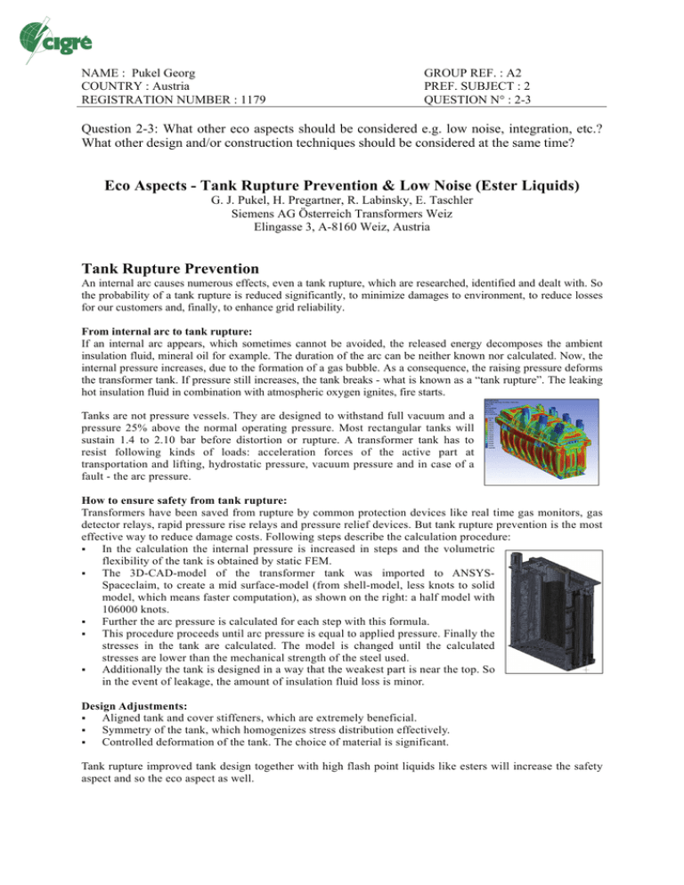
NAME : Pukel Georg COUNTRY : Austria REGISTRATION NUMBER : 1179 GROUP REF. : A2 PREF. SUBJECT : 2 QUESTION N° : 2-3 Question 2-3: What other eco aspects should be considered e.g. low noise, integration, etc.? What other design and/or construction techniques should be considered at the same time? Eco Aspects - Tank Rupture Prevention & Low Noise (Ester Liquids) G. J. Pukel, H. Pregartner, R. Labinsky, E. Taschler Siemens AG Österreich Transformers Weiz Elingasse 3, A-8160 Weiz, Austria Tank Rupture Prevention An internal arc causes numerous effects, even a tank rupture, which are researched, identified and dealt with. So the probability of a tank rupture is reduced significantly, to minimize damages to environment, to reduce losses for our customers and, finally, to enhance grid reliability. From internal arc to tank rupture: If an internal arc appears, which sometimes cannot be avoided, the released energy decomposes the ambient insulation fluid, mineral oil for example. The duration of the arc can be neither known nor calculated. Now, the internal pressure increases, due to the formation of a gas bubble. As a consequence, the raising pressure deforms the transformer tank. If pressure still increases, the tank breaks - what is known as a “tank rupture”. The leaking hot insulation fluid in combination with atmospheric oxygen ignites, fire starts. Tanks are not pressure vessels. They are designed to withstand full vacuum and a pressure 25% above the normal operating pressure. Most rectangular tanks will sustain 1.4 to 2.10 bar before distortion or rupture. A transformer tank has to resist following kinds of loads: acceleration forces of the active part at transportation and lifting, hydrostatic pressure, vacuum pressure and in case of a fault - the arc pressure. How to ensure safety from tank rupture: Transformers have been saved from rupture by common protection devices like real time gas monitors, gas detector relays, rapid pressure rise relays and pressure relief devices. But tank rupture prevention is the most effective way to reduce damage costs. Following steps describe the calculation procedure: In the calculation the internal pressure is increased in steps and the volumetric flexibility of the tank is obtained by static FEM. The 3D-CAD-model of the transformer tank was imported to ANSYSSpaceclaim, to create a mid surface-model (from shell-model, less knots to solid model, which means faster computation), as shown on the right: a half model with 106000 knots. Further the arc pressure is calculated for each step with this formula. This procedure proceeds until arc pressure is equal to applied pressure. Finally the stresses in the tank are calculated. The model is changed until the calculated stresses are lower than the mechanical strength of the steel used. Additionally the tank is designed in a way that the weakest part is near the top. So in the event of leakage, the amount of insulation fluid loss is minor. Design Adjustments: Aligned tank and cover stiffeners, which are extremely beneficial. Symmetry of the tank, which homogenizes stress distribution effectively. Controlled deformation of the tank. The choice of material is significant. Tank rupture improved tank design together with high flash point liquids like esters will increase the safety aspect and so the eco aspect as well. Low Noise Transformers are now, more than ever, located where acoustic environmental protection is of crucial significance. Limited space in cities and strict noise performance requirements create extra efforts in building power transformers. The load noise emitted by energized transformers consists of noload noise, load current induced noise and cooling equipment noise. The reduction of core vibration, a classic noise source, is a major task in low noise transformer design. DC - magnetization must be considered to avoid amplification of core vibration. The biggest challenge was the development of a calculation method for load current noise as the understanding of load current effects is the basis for noise cancellation activities. Calculation models relating to magnetic forces, magnetostriction and dynamic mechanical models, in particular, brought the break through innovation and desired noise reduction results. Standard transformer design vs. low noise transformer design/420 MVA/sound pressure condition 100% Urated no-load 100% Irated load current fans, pumps cooler TOTAL Note: standard design dB(A) 65.5 70.3 74.5 76.3 low noise design dB(A) 46.5 51.1 39.2 52.4 noise reduction dB(A) - 19.0 - 19.2 - 35.3 - 23.9 420 MVA autotransformer, emits only 52.4 dB(A) For the human ear 56 dB(A) sound pressure level is comparable with a domestic refrigerator. Sound intensity measurement method is 2 - 4 dB(A) below sound pressure method. Low noise and ester liquids Significant differences in the dielectric and thermal behavior between mineral oil and environmentally friendly ester liquids lead to specific designs for ester filled transformers. Even for these designs our noise calculation programs deliver low noise optimized designs.


