encor e!n etworks
•
TM
Version A, January 2012
© 2012 Encore Networks, Inc.
All rights reserved.
Using a Three-Pronged DC Power Connector
with a BANDIT II C2C
T
his document describes assembly and use of a three-pronged DC power connector for
Encore Networks, Inc.’s family of BANDIT™ chassis. The steps also include connection to
AC power, for review.
The three-pronged DC connector is used in the following BANDIT chassis.
• BANDIT II chassis (DC model)
• BANDIT II C2C chassis (DC model)
!
Caution: If you have a BANDIT chassis that can use both DC and AC power, it is important
to follow these steps to connect all power sources to that chassis.
If you ordered a BANDIT chassis that uses a three-pronged connector for DC input power, the
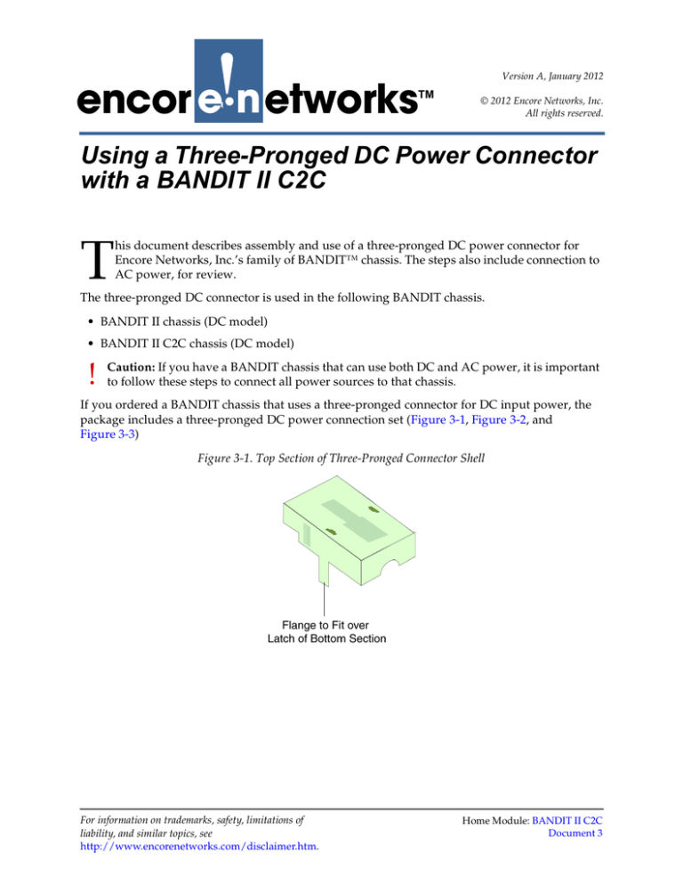
package includes a three-pronged DC power connection set (Figure 3-1, Figure 3-2, and
Figure 3-3)
Figure 3-1. Top Section of Three-Pronged Connector Shell
For information on trademarks, safety, limitations of
liability, and similar topics, see
http://www.encorenetworks.com/disclaimer.htm.
Home Module: BANDIT II C2C
Document 3
Page 2
BANDIT II C2C Module, Document 3
Figure 3-2. Three-Pronged DC Power Connector
Figure 3-3. Bottom Section of Three-Pronged Connector Shell
To connector your BANDIT device to a DC power source, perform the following procedure.
Use the following steps to connect cables to user equipment and prepare the BANDIT chassis
for configuration and use.
Note: See the BANDIT II C2C Hardware Description and Specifications for diagrams of the
chassis and the ports.
1
Place the BANDIT chassis on a tabletop or shelf.
Note: Make sure there is sufficient room above and below the chassis for ventilation
and cooling. See the requirements in Ventilation for BANDIT Products.
2
Connect an earth ground wire to the chassis, as follows: Attach a (minimum) 12 AWG
wire to the earth ground bolt (next to the safety ground symbol), on the back of the
chassis. Use a ring terminal, such as an AMP (part number 36160), for this connection.
Warning: An earth ground must connect to the chassis so that the chassis remains
grounded even when it is not receiving power.
3
Connect the BANDIT chassis’s ports to their network devices. For example, connect the
LAN ports, WAN port, modem port, serial port(s), and expansion port to the network
devices, as follows:
Warning: If you need to disable the BANDIT devices’s plug-and-play mode, do not
connect the WAN port or the LAN ports to equipment until after you have completed
this entire procedure.1
a Use an Ethernet 10-Base-T cable to connect the WAN port to the WAN equipment.
b Use an Ethernet 10-Base-T cable to connect each LAN port to its equipment.
c If your BANDIT chassis uses IDU™ or RDU™ serial ports, connect the IDU or RDU
serial ports to the network equipment.
1. Plug-and-play mode is disabled by default in all BANDIT chassis except the BANDIT IP.
Using a Three-Pronged DC Power Connector with a BANDIT II C2C
Page 3
d Connect the dial backup modem port to the RJ11 phone jack you plan to use. (Encore
Networks does not supply the modem cable.)
e Connect additional network equipment to the remaining ports on the BANDIT device.
This includes any port in the expansion slot.
4
Use a DB9-to-DB9 cable to connect the device’s DB9 Supervisory port to your PC’s DB9
port.
5
If the BANDIT chassis will use only AC input power, go to Step 12.
6
If the BANDIT chassis will use DC input power, connect the chassis to a power source
supplying -12/-24 VDC or -24/-48 VDC, as described in Step 7 through Step 11.
Note: The power source must supply -12/-24 VDC or -24/-48 VDC.
7
Make sure the BANDIT chassis is disconnected from all power sources.
8
Make sure an earth ground wire is connected to the chassis frame, as described in
Step 2.
9
Do the following:
a Turn the DC power connector (the DC power plug) on its side, with the screwheads
facing your left and with the prongs pointing away from you (as shown in Figure 3-4).
Figure 3-4. Three-Pronged DC Power Connector, on Side
b Note the following:
• The top post has no connection (NC).
• The middle post is − (for the negative/return wire).
• The bottom post is + (for the positive wire).
c Connect a (minimum) 14 AWG two-wire input cable to the green three-pin DC power
connector (that is, the DC power plug). Make sure you connect the correct wire to each
post. Figure 3-5 shows the plug with the cables attached.
Figure 3-5. Three-Pronged DC Power Connector with Wires
Page 4
BANDIT II C2C Module, Document 3
10 A shell cover is provided with the DC power connector, to provide strain relief for the
wires. Restrain the wires against the lower half of the shell, and place the shell around
the connector, as described in the following substeps:
a Seat the DC power connector (the plug) into the bottom half of the shell. The connector
will seat into the shell in only one way, as shown in Figure 3-6.
Figure 3-6. Cabled Three-Pronged DC Power Connector and
Bottom Section of Shell
Note: The top and bottom sections of the shell differ. The top section (recall Figure 3-1)
has flanges to fit against the bottom section’s latches (recall Figure 3-3).
b With the plug seated into the bottom section, place the top section of the shell onto the
bottom section. Do not yet snap them into place. (Figure 3-7 shows how the top and
bottom sections fit together around the DC power plug.)
Using a Three-Pronged DC Power Connector with a BANDIT II C2C
Page 5
Figure 3-7. Top Section of Shell above Cabled Three-Pronged
DC Power Connector and Bottom Section
c Make sure the DC power connector sits properly in the bottom section. Then snap the
top and bottom sections together, as shown in Figure 3-8.
Note: Make sure the cables go through the cable hole.
Figure 3-8. Closed Three-Pronged DC Shell Assembly
Note: If you need to take the case apart, grasp each flange of the top section and gently
pull them away from the latches on the bottom section. Then pull the top section off
the bottom section. Repeat Step 10a through Step 10c to reassemble the connector case.
11 When the shell assembly has snapped into place around the DC plug, do the following:
a Flanges on the plug (Figure 3-9) allow it to fit into the three-pronged DC power input
port on the backplate of the BANDIT chassis in only one way.
Page 6
BANDIT II C2C Module, Document 3
Note: To review the orientation of the three-pronged DC power input port, see the
following:
• Figure A-2 or Figure A-3 in Section A.1, The BANDIT II C2C Chassis, in the BANDIT II
C2C Hardware Description and Specifications).
You may need to turn the plug over to fit it into the port. If this is the case, rotate the
shell assembly 180° around the axis corresponding to the DC power cable (Figure 3-9
and Figure 3-10).
Figure 3-9. Rotate Three-Pronged DC Shell Assembly 180 Degrees
around Axis of Power Cable
Figure 3-10. Three-Pronged DC Shell Assembly Rotated 180 Degrees
b Plug the DC power connector (the shell plug) into the DC power input port on the rear
of the BANDIT chassis.
c Then connect the other end of the DC power cable to a -24/-48 volt DC or -12/-24 volt
DC power source.
Note: The power source must supply -12/-24 VDC or -24/-48 VDC.
!
Caution: The DC power source must match the DC input power rating indicated on
the BANDIT chassis.
❖ The BANDIT chassis powers up.
12 If the BANDIT chassis will use AC input power (instead of DC power or in addition to
DC power), connect the AC power supply to the chassis, and then connect the AC
power supply to a power outlet supplying 100–240 VAC at 47–63 Hz.
❖ The BANDIT chassis powers up.
Using a Three-Pronged DC Power Connector with a BANDIT II C2C
Page 7
13 The BANDIT chassis’s hardware installation is complete. Return to the installation
guide for your BANDIT chassis:
• BANDIT II C2C: BANDIT II C2C Quick Installation Guide
Page 8
BANDIT II C2C Module, Document 3


