TeSys IEC Contactors
and Overload Relays
Making High-Fault Short-Circuit Current Ratings Simple
Schneider Electric is an industry leader in IEC contactors and overload relays, and
is recognized as the market leader in quality, durability, and product development.
The latest development in the TeSys™ family of IEC contactors and overload
relays is component high-fault short-circuit current ratings (SCCRs).
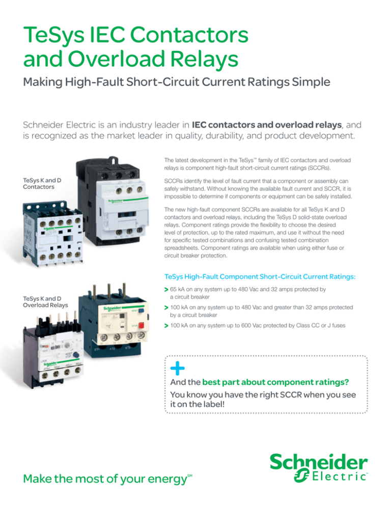
TeSys K and D
Contactors
SCCRs identify the level of fault current that a component or assembly can
safely withstand. Without knowing the available fault current and SCCR, it is
impossible to determine if components or equipment can be safely installed.
The new high-fault component SCCRs are available for all TeSys K and D
contactors and overload relays, including the TeSys D solid-state overload
relays. Component ratings provide the flexibility to choose the desired
level of protection, up to the rated maximum, and use it without the need
for specific tested combinations and confusing tested combination
spreadsheets. Component ratings are available when using either fuse or
circuit breaker protection.
TeSys High-Fault Component Short-Circuit Current Ratings:
TeSys K and D
Overload Relays
65 kA on any system up to 480 Vac and 32 amps protected by
a circuit breaker
100 kA on any system up to 480 Vac and greater than 32 amps protected
by a circuit breaker
100 kA on any system up to 600 Vac protected by Class CC or J fuses
And the best part about component ratings?
You know you have the right SCCR when you see
it on the label!
Make the most of your energy
SM
TeSys K and D Contactors and Overload Relays
TeSys D Overload Relays — Solid State
Class 20
Maximum Component SCCR[1]
Class
Circuit Breakers
10 or 20
Fuses @ 600 V[3]
@ 480 V[2]
Selectable
Max. SCCR (kA) Max. SCCR (kA)
D115 – D150 LR9D5367
LR9D5567
LR9D67
100
100
D115 – D150 LR9D5369
LR9D5569
LR9D69
100
100
Current
Setting
Range (A)
For Direct
Mounting to
LC1…
60 – 100
90 – 150
Class 10
Ratings apply to circuits with voltages no greater than those listed and are subject to maximum breaker and fuse ampacities. See data
bulletin 8536DB0901 for ampacity limitations.
[2]
When protected by any circuit breaker, including thermal-magnetic and magnetic-only.
[3]
When protected by any Class J time-delay fuse.
[1]
©2012 Schneider Electric. All Rights Reserved. All trademarks are owned by Schneider Electric Industries SAS or its affiliated companies. 998-1176922_US
Note: This table lists the maximum SCCR of the component when protected by any circuit breaker or fuse. If the maximum component SCCR
is 100 kA and a 25 kA rated circuit breaker is used, then the system will be 25 kA as the circuit breaker becomes the weakest link.
For more information on high-fault component short-circuit current ratings
including maximum fuse and breaker ampacities, please refer to the TeSys Motor
Control Solutions for the North American Market data bulletin (8536DB0901).
Schneider Electric USA
1415 S. Roselle Road
Palatine, IL 60067
Tel: 847-397-2600
Fax: 847-925-7500
www.schneider-electric.com/us
Document Number 8502HO1201
October 2012
TeSys™ D-Line Contactors and Starters
LR9D 3-pole Solid-state Overload Relays
LR9D 3-pole Solid-state Overload Relays
Description
LR9D electronic thermal overload relays are designed for use with contactors LC1D115 and D150.
In addition to the protection provided by model d thermal overload relays, (see page 130), they offer the following special features:
k Protection against phase imbalance.
k Choice of starting class.
k Protection of unbalanced circuits.
k Protection of single-phase circuits.
k Alarm function to avoid tripping by load shedding.
LR9D5367 to D5569
LR9D67 and D69
7
8
2
1
2
1 Setting dial Ir
2 Test button
3 Stop button
4 Reset button
5 Trip indication
6 Setting locked by sealing the cover
7 Class 10/class 20 selector
8 Selector for balanced load
/
unbalanced load
5
4
3
Ir(A)
127
107
90
Class
127
NO
97
95
NC
10
+
150
98
5
4
3
Load
Ir(A) 20
107
90
96
24 V - / 103
150
104
Alarm
98
NO
97
95
NC
96
1
6
6
Environment
Conforming to standards
IEC 60947-4-1, 255-8, 255-17, VDE 0660 and EN 60947-4-1
Product certifications
UL 508, CSA 22-2
Degree of protection
Conforming to IEC 60529 and VDE 0106
IP 20 on front face with protective covers LA9D11570• or D11560•
Protective treatment
Standard version
Ambient air temperature around the device
(conforming to IEC 60255-8)
Storage
°C
Normal operation
°C
- 20 to + 55 (1) (- 68 to + 131 °F)
Maximum operating altitude
Without derating
ft/m
6562 (2000)
“TH”
- 40 to + 85 (- 104 to + 185 °F)
Operating positions without derating
In relation to normal, vertical mounting plane
Any position
Shock resistance
Permissible acceleration conforming to
IEC 60068-2-27
13 gn - 11 ms
Vibration resistance
Permissible acceleration conforming to
IEC 60068-2-6
2 gn - 5 to 300 Hz
Dielectric strength at 50 Hz
Conforming to IEC 60255-5
kV
6
Impulse withstand voltage
Conforming to IEC 61000-4-5
kV
6
Resistance to electrostatic discharge
Conforming to IEC 61000-4-2
kV
8
Resistance to radio-frequency
conducted disturbances
Conforming to IEC 61000-4-3 and
NF C 46-022
V/m
10
Resistance to fast transient currents
Conforming to IEC 61000-4-4
kV
2
Electromagnetic compatibility
Draft EN 50081-1 and 2, EN 50082-2
V
Meets requirements
Electrical characteristics of auxiliary contacts
Conventional thermal current
ac supply
Maximum consumption
of operating coils
of controlled contactors
(Occasional operating cycles of contact 95-96)
dc supply
A
5
V
24
48
110
220
380
600
VA
100
200
400
600
600
600
V
24
48
110
220
440
–
W
100
100
50
45
25
–
Short-circuit protection k
By gG, BS or Class CC fuse or by GB2 circuitA
breaker
Cabling
One or two conductors
AWG
(mm2)
Minimum c.s.a.: 16 (1) / maximum c.s.a.: 14 (2.5)
Flexible cable without cable end
Tightening torque
lb-in
(N.m)
11 (1.2)
(1)
k
5
For operation at 70 °C (158 °F), please consult your Regional Sales Office.
Select short circuit protection to meet the National Electrical Code or other local codes and standards.
Catalog Numbers: pages 135
Dimensions: pages 138
132
© 2001-2004 Schneider Electric All Rights Reserved
01/04
TeSys™ D-Line Contactors and Starters
LR9D 3-pole Solid-state Overload Relays
Electrical Characteristics of Power Circuit
Relay Type
LR9-D
Conforming to UL 508,
IEC 60947-4-1
Conforming to IEC 60947-4-1
Conforming to UL, CSA
Tripping Class
Rated Insulation Voltage (Ui)
Rated Impulse Withstand Voltage
(Uimp)
Frequency Limits
Setting Range
10 or 20
1000 V
600 V
8 kV
Of the operational current
Depending on model
Width of terminal lug
Clamping screw
Tightening torque
Power Circuit Connections
50-60 Hz For other frequencies, consult your Regional Sales Office. (1)
60-150 A
0.787 in (20 mm)
M8
lb-ft 13 (18 N•m)
Operating Specifications
Temperature Compensation
Tripping Threshold
-20 to +70 °C (- 68 to + 158 °F)
Conforming to IEC 60947-4-1
Alarm
Tripping
Conforming to IEC 60947-4-1
Sensitivity to Phase Failure
1.05 ± 0.06 In A
1.12 ± 0.06 In A
Tripping current 4 s ± 20% in the event of phase failure
Alarm Circuit Specifications
Rated Supply Voltage
Supply Voltage Limits
Current Consumption
Switching Capacity
Protection
Voltage Drop
Cabling
Tightening Torque
dc supply
24 Vdc
17 - 32 V
less than or equal to 5 mA
0 - 150 mA
Self-protected
less than or equal to 2.5 V
20 - 16 AWG (0.5 - 1.5 mm2)
4.0 lb-in (0.45 N•m)
No load
Short-circuit and overload
Closed state
Flexible cable without cable end
Tripping Curve LR9-D
Average Operating Time Related to Multiples of the Current Setting
Tripping time in seconds
000
100
1
2
10
1
0
1 1.12 2
3
4
5
6
7
8
9
10
11
12
x the current setting (ir)
1
2
(1)
Cold state curve.
Hot state curve.
For use of these relays with soft start units or variable speed controllers, please consult your Regional Sales Office.
Catalog Numbers: pages 135
01/04
Dimensions: pages 138
© 2001-2004 Schneider Electric All Rights Reserved
133
TeSys™ D-Line Contactors and Starters
Selection of 3-pole Class 20 Bimetallic and Class 10 Solid-state Overload Relays
Selection of 3-pole Class 20 Bimetallic and Class 10 Solid-state Overload Relays
Differential (Single Phase Sensitive) Thermal Overload Relays
Compensated relays with manual or automatic reset, with relay trip indicator, for ac or dc
LR2-D1508 to 2553: independent mounting either by ordering a terminal block LA7D1064 or LA7D2064, or by ordering the relay pre-assembled; in this
case, add the suffix LA7 to the reference.
Example: LR2D1508 becomes LR2D1508LA7.
Short-circuit Protection for North American Applications
Relay Setting
Range
A
Fuses to be used with
the Selected Relay
By Circuit Breaker
Select in Accordance with NEC and Local Codes
By Fuses
Maximum 400% of Motor FLA
For use with Contactor
aM
gG
BS88
A
A
A
Catalog Number
Weight lb. (kg)
LC1
Class 20 for Connection by Screw Clamp Terminals
LRD15
2.5 to 4
6
10
16
D09 to D38 (2)
LRD1508 (3)
0.42 (0.190)
4 to 6
8
16
16
D09 to D38 (2)
LRD1510 (3)
0.42 (0.190)
5.5 to 8
12
20
20
D09 to D38 (2)
LRD1512 (3)
0.42 (0.190)
7 to 10
16
20
25
D09 to D38 (2)
LRD1514 (3)
0.42 (0.190)
9 to 13
16
25
25
D12 to D38 (2)
LRD1516 (3)
0.42 (0.190)
12 to 18
25
35
40
D18 to D38 (2)
LRD1521 (3)
0.42 (0.190)
17 to 25
32
50
50
D25 and D38 (2)
LRD1522 (3)
0.42 (0.190)
23 to 28
40
63
63
D25 and D38 (2)
LRD1530 (3)
0.76 (0.345)
25 to 32
40
63
63
D25 and D38 (2)
LRD1532 (3)
0.76 (0.345)
17 to 25
32
50
50
D40 to D95
LRD3522
1.18 (0.535)
23 to 32
40
63
63
D40 to D95
LR2D3553
1.18 (0.535)
30 to 40
50
100
80
D40 to D95
LR2D3555
1.18 (0.535)
37 to 50
63
100
100
D50 to D95
LR2D3557
1.18 (0.535)
48 to 65
80
125
100
D50 to D95
LR2D3559
1.18 (0.535)
55 to 70
100
125
125
D65 to D95
LR2D3561
1.18 (0.535)
63 to 80
100
160
125
D80 and D95
LR2D3563
1.18 (0.535)
Solid-state Differential Thermal Overload Relays
Compensated relays, with relay trip indicator, for ac or dc, for direct mounting on contactor or independent mounting (1).
Relay Setting
Range
Fuses to be used with Selected Relay (4) For Direct Mounting
Beneath Contactor LC1
aM
gG
A
A
Catalog Number
Weight lb. (kg)
A
Class 10 for Connection using Bars or Connectors
60 to 100
100
160
D115 and D150
LR9D5367
1.95 (0.885)
90 to 150
160
250
D115 and D150
LR9D5369
1.95 (0.885)
Class 20 for Connection using Bars or Connectors
60 to 100
125
160
D115 and D150
LR9D5567
1.95 (0.885)
90 to 150
200
250
D115 and D150
LR9D5569
1.95 (0.885)
Solid-state Thermal Overload Relays for use with Balanced/Unbalanced Loads (Single Phase)
Compensated relays, with separate outputs for alarm and tripping.
LR2D35
Relay Setting
Range
Fuses to be used with Selected Relay (4) For Direct Mounting
Beneath Contactor LC1
aM
gG
A
A
Catalog Number
Weight lb. (kg)
A
Class 10 or 20 Selectable with Connection using Bars or Connectors
60 to 100
100
160
D115 and D150
LR9D67
1.98 (0.900)
90 to 150
160
250
D115 and D150
LR9D69
1.98 (0.900)
(1)
(2)
(3)
(4)
Power terminals can be protected against direct finger contact by the addition of shrouds and/or insulated terminal blocks, to be ordered separately
(see page 113).
For use with D25-D38 contactors, order spacer clip (part number W816366180111). See page 137.
These overloads are available without single phase sensitivity. To order, change the LRD prefix to LR3D and add A1 to the end of the number.
Example: LRD1508 becomes LR3D1508A1
Select short circuit protection to meet the National Electrical Code or other local codes and standards.
Other Versions
01/04
Thermal overload relays for resistive circuits in category AC-1. Please consult your Regional Sales Office.
© 2001-2004 Schneider Electric All Rights Reserved
135


