Caution: Risk of Electric Shock
advertisement

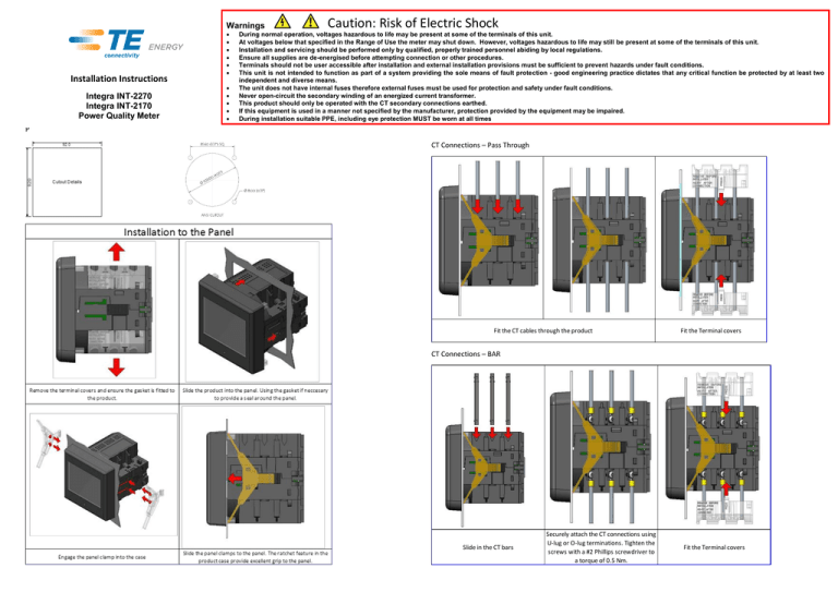
Warnings Installation Instructions Integra INT-2270 Integra INT-2170 Power Quality Meter Caution: Risk of Electric Shock During normal operation, voltages hazardous to life may be present at some of the terminals of this unit. At voltages below that specified in the Range of Use the meter may shut down. However, voltages hazardous to life may still be present at some of the terminals of this unit. Installation and servicing should be performed only by qualified, properly trained personnel abiding by local regulations. Ensure all supplies are de-energised before attempting connection or other procedures. Terminals should not be user accessible after installation and external installation provisions must be sufficient to prevent hazards under fault conditions. This unit is not intended to function as part of a system providing the sole means of fault protection - good engineering practice dictates that any critical function be protected by at least two independent and diverse means. The unit does not have internal fuses therefore external fuses must be used for protection and safety under fault conditions. Never open-circuit the secondary winding of an energized current transformer. This product should only be operated with the CT secondary connections earthed. If this equipment is used in a manner not specified by the manufacturer, protection provided by the equipment may be impaired. During installation suitable PPE, including eye protection MUST be worn at all times P CT Connections – Pass Through Fit the CT cables through the product Fit the Terminal covers CT Connections – BAR Slide in the CT bars Securely attach the CT connections using U-lug or O-lug terminations. Tighten the screws with a #2 Phillips screwdriver to a torque of 0.5 Nm. Fit the Terminal covers Voltage, Power Supply and Input / Output Connections Fixing and Installation Kit (Supplied) While TE has made every reasonable effort to ensure the accuracy of the information in this catalogue, TE does not guarantee that it is error-free, nor does TE make any other representation, warranty or guarantee that the information is accurate, correct, reliable or current. TE reserves the right to make any adjustments to the information contained herein at any time without notice. TE expressly disclaims all implied warranties regarding the information contained herein, including, but not limited to, any implied warranties of merchantability or fitness for a particular purpose. The dimensions in this catalogue are for reference purposes only and are subject to change without notice. Specifications are subject to change without notice. Consult TE for the latest dimensions and design specifications. TE connectivity (logo), TE (logo) and TE Connectivity are trademarks of the TE Connectivity Ltd. family of companies. Crompton is a trademark of Crompton Parkinson and is used by TE Connectivity under a licence. Other logos, product and company names mentioned herein may be trademarks of their respective owners TE Energy – innovative and economical solutions for the electrical power industry: cable accessories, connectors & fittings, insulators & insulation, surge arresters, switching equipment, street lighting, power measurement and control. Tyco Electronics UK Ltd TE Energy Freebournes Road Witham, Essex CM8 3AH Phone: +44 (0)870 870 7500 Fax: +44 (0)870 240 5289 Email: Crompton.info@te.com www.crompton-instruments.com Project 2225. Drawing No. CI-3K84305 Rev.3 DMR 29/01/15


