R1.6 Hynds Concrete Water Tanks
advertisement
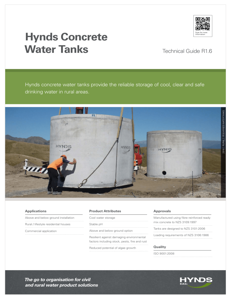
Hynds Concrete Water Tanks Scan for more information Technical Guide R1.6 2016 | RURAL | R1.6 Hynds Water Tanks Hynds concrete water tanks provide the reliable storage of cool, clear and safe drinking water in rural areas. Applications Product Attributes Approvals Above and below ground installation Cool water storage Manufactured using fibre reinforced ready Rural / lifestyle residential houses Stable pH Commercial application Above and below ground option Resilient against damaging environmental mix concrete to NZS 3109:1997 Tanks are designed to NZS 3101:2006 Loading requirements of NZS 3106:1986 factors including stock, pests, fire and rust Reduced potential of algae growth Quality ISO 9001:2008 The go to organisation for civil and rural water product solutions Hynds concrete water tanks offer a long and virtually maintenance free service life. Hynds tanks are strong and durable. Tanks Specifications and Capacities ■■ ■■ ■■ ■■ R1.6 Hynds Water Tanks | RURAL | PG 2 ■■ Above ground water tanks are designed to be either free standing above the ground or partially buried 300 - 500 mm from underside of tank. Fully buried (flat top) tanks are designed to be buried with a maximum of 300 mm of earth cover. Tank capacity is 22,700 litres (5,000 gallons). Other than the earth cover, buried water tanks cannot be driven on, or take any external loading, live or static within a distance of 3.2 metres to the nearest edge of the tank. No traffic loading Load requirements Tank Venting An insect proof vent is installed in the centre of the tank lid. Vent airflow ensures that neither a vacuum or excess air pressure will develop in the tank. Pumping water from the tank requires air to replace the water and water entering the tank requires that air be displaced. A non venting tank will reduce your pump performance. Tanks Access A 600 mm raised manhole access on the top of the lid ensures that any material that is present on the tank lid cannot be washed into the tank via access. This access has a concrete lid that can be bolted shut to give added security. For correct loading and unloading on to trucks, please refer to loading instructions (available on request). Table 1 Tank Dimensions Product Code Description Height Width (mm) (mm) Ground to bottom of invert Outlet fitting Weight (T) Capacity (ltr) (mm) SOUTH ISLAND - HORNBY/AMBERLEY WT5000LDL Water tank conc Elite 22,730L cw above ground lid 2905 3800 850 50 11.05 22,730 WT5000HDL Water tank conc Elite 22,730L cw below ground lid 2860 3800 850 50 11.05 22,730 NORTH ISLAND - EAST TAMAKI WT5000ELT-P Water tank conc Elite 22,730L cw above ground lid 2928 3870 850 50 9.24 22,730 WT5000ELTFT-P Water tank conc Elite 22,730L cw below ground lid 2790 3870 850 50 9.24 22,730 Table 2 Concrete Water Tank Accessories Code Description RHCONTV090 Marley Vacuum Kit for Concrete Tanks RHCI Marley Calmed Inlet RHFO Marley Floating Outtake WATERLEVEL Water Level Indicator WATERLEVEL + EXT Water Level Indicator Meter Extension RHMG Marley Mechanical Water Gauge Female Tank Fittings Male Tank Fittings Code Code Dia (mm) Brass Tank Fittings Dia Code (mm) Dia (mm) LDF-TFFB 15 LDF-TFMB15 15 BTS20 20 LDF-TFFB 20 LDF-TFMB20 20 BTS25 25 LDF-TFFB 25 LDF-TFMB25 25 BTS32 32 LDF-TFFB 32 LDF-TFMB32 32 BTS40 40 LDF-TFFB 40 LDF-TFMB40 40 BTS50 50 LDF-TFFB 50 LDF-TFMB50 50 Why Concrete Is Better Concrete tanks provide greater insulation from heat and light and therefore the water temperature is maintained at a more constant temperature which decreases the growth of bacteria and algae in water storage tanks. Water Quality Construction ■■ Excellent pH (medium 7.5) ■■ Non corrosive robust construction ■■ Good insulation for cool water ■■ Brass fittings ■■ 45 MPa concrete Tank Installation Above ground tanks Concrete tanks can be either fully or partially buried to increase the aesthetics of a site. ■■ ■■ ■■ Tanks must not be installed in such a way that only one side of the tank is restraining the backfilled earth. In these situations drain-coil and drainage metal must be placed directly next to the tank to ensure no hydrostatic pressure builds up against the tank wall. ■■ ■■ ■■ Buried tanks should not be backfilled until the water tightness of all connections is tested. It is recommended that all tank outlets be fitted with a shut off valve as close as practical to the tank. It is recommend that your tank has an overflow outlet and this is piped well clear of the tank foundations. A standard tank can be set in the ground to within 500 mm from underside of tank. ■■ Other than the earth cover, buried water tanks cannot be driven on, or take any external loading, live or static within a distance of 3.2 metres to the nearest edge of the tank. Sites with high water tables may require tanks with flanged boxes to prevent flotation. Installation ■■ ■■ Inlet connections (top): If a tank is to be fully buried a ‘Flat Top’ tank is required. These have a flat roof and a support pillar in the centre of the tank. Flat Top water tanks can only be buried to a maximum depth of 300 mm below ground level or a maximum overburden loading of 10 kPa. ■■ Connections The tank will float if the local groundwater rises over 900 mm from the bottom of the tank. Buried Tanks ■■ Tanks cannot be placed within 3 metres at a building or structure and 3 metres from boundary or trafficed area. Tanks must always be placed on a bed of compacted sand or fine aggregate of a similar grade, screeded level to a minimum thickness of 50 mm to a maximum of 150 mm. The base should be approximately 1 metre greater in diameter than the tank to ensure a consistent transferring of the tank weight to the ground. Multiple tanks are to have at least 1500 mm distance between them. No bushes, tree, or power lines are to pass underneath or adjacent to within a minimum of 2 metres of the water tank wall. ■■ 2 x 100 mm – located at opposite ends. Outlet connections: ■■ 2 x 50 mm – located at same end. Note: One connection is capped and the second threaded male connection is bare. This is bare for fitting of the shut-off valve. See your plumber for connection information. Tank Filling A new above ground water tank should never be filled completely to the top in one step as this may cause stress cracks. The recommended procedure is: ■■ Fill approximately one quarter. ■■ Leave for two days. ■■ Fill another quarter. ■■ Leave for another two days. ■■ Continue process until tank is filled. This allows the reinforcing in the tank walls to expand gradually. Partially and buried tanks should be filled in two steps similar to the above ground tank. Unconnected or used tanks should not be left empty. There should be 300 mm of water left in the bottom of the tank at all times. R1.6 Hynds Water Tanks | RURAL | PG 3 ■■ For partially buried tanks, the area surrounding the tank must be free draining. ■■ Installation Guidelines Site Access ■■ ■■ ■■ ■■ ■■ ■■ R1.6 Hynds Water Tanks | RURAL | PG 4 ■■ ■■ ■■ ■■ Site Clearance Requirements Access to the site must have adequate width clearance to allow the truck unrestricted height and turning entry to the site. Weight of truck and tank can be up to 22 tonnes. The site must be level and free from any obstructions such as large rocks. The site foundation must be completely solid so as to disperse the truck weight evenly. Hiab stabilising arms must also be allowed for on site. The arms extend 2.5 metres either side of the truck. The site must also be clear of overhead wires a minimum of 4 metres from the Hiab hook at all times. For partially buried tanks the centre of the tank cannot be further than 5 metres from the position of the truck rear wheels. Allowance must be made for excavation batters in this measurement. For fully buried tanks the centre of the tank cannot be further than 4 metres from the position of the truck rear wheels. Allowance must be made for excavation batters in this measurement. The excavated hole must be stable and safe before off loading of the tank can commence. Tanks cannot be placed on-site higher than the truck deck height or 1200 mm. If placement of the tanks is outside these measurements, the tanks will require a special on-site crane for placement which is at the cost of the purchaser. Fig. 1 Above Ground Note: Should the delivery contractor experience conditions outside the above requirements, or other factors that delay the off loading of the tanks, the client will be charged on an hourly rate for the cost of these delays. Site Preparation ■■ ■■ ■■ The Hynds Water Tank must be installed on solid ground capable of taking the weight of the tank and water contents (31.5 tonnes). In accordance with NZS 3604. Fig. 2 Below Ground The material forming the tank foundations must have a safe bearing capacity of 100 kPa (Normal house foundations). Under no circumstances can any part of the tank be installed on fill material or be part of a retaining structure. Refer to table 1 for dimensions Branches Nationwide Support Office & Technical Services 09 274 0316 Disclaimer: While every effort has been made to ensure that the information in this document is correct and accurate, users of Hynds product or information within this document must make their own assessment of suitability for their particular application. Product dimensions are nominal only, and should be verified if critical to a particular installation. No warranty is either expressed, implied, or statutory made by Hynds unless expressly stated in any sale and purchase agreement entered into between Hynds and the user.

