DATASHEET
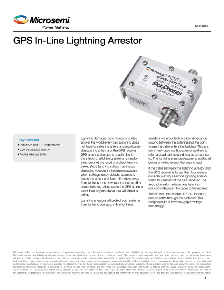
GPS In-Line Lightning Arrestor
Key Features
• Industry's best RF Performance
• Low throughput energy
• Multi-strike capability
Lightning damages communications sites
all over the world every day. Lightning does
not have to strike the antenna to significantly
damage the antenna or the GPS receiver.
GPS antenna damage is usually due to
the effects of a lightning strike on a nearby
structure, not the result of a direct lightning
strike. Since lightning strikes may induce
damaging voltages in the antenna system
when striking nearby objects, attempt to
locate the antenna at least 15 meters away
from lightning rods, towers, or structures that
attract lightning. Also, locate the GPS antenna
lower than any structures that will attract a
strike.
Lightning arrestors will protect your systems
from lightning damage. In-line lightning
arrestors are mounted on a low impedance
ground between the antenna and the point
where the cable enters the building. This is a
commonly used configuration since there is
often a good earth ground nearby to connect
to. The lightning arrestors require no additional
power or wiring except the ground lead.
If the cable between this lightning arrestor and
the GPS receiver is longer than four meters,
consider placing a second lightning arrestor
within four meters of the GPS receiver. The
second arrestor reduces any lightninginduced voltages in the cable to the receiver.
These units use separate RF (DC-Blocked)
and dc paths through the protector. This
design results in low throughput voltage
and energy.
Microsemi makes no warranty, representation, or guarantee regarding the information contained herein or the suitability of its products and services for any particular purpose, nor does
Microsemi assume any liability whatsoever arising out of the application or use of any product or circuit. The products sold hereunder and any other products sold by Microsemi have been
subject to limited testing and should not be used in conjunction with mission-critical equipment or applications. Any performance specifications are believed to be reliable but are not verified, and Buyer must conduct and complete all performance and other testing of the products, alone and together with, or installed in, any end-products. Buyer shall not rely on any data and
performance specifications or parameters provided by Microsemi. It is the Buyer’s responsibility to independently determine suitability of any products and to test and verify the same. The information
provided by Microsemi hereunder is provided “as is, where is” and with all faults, and the entire risk associated with such information is entirely with the Buyer. Microsemi does not grant, explicitly or implicitly, to any party any patent rights, licenses, or any other IP rights, whether with regard to such information itself or anything described by such information. Information provided in
this document is proprietary to Microsemi, and Microsemi reserves the right to make any changes to the information in this document or to any products and services at any time without notice.
1
DATASHEET
GPS In-Line Lightning Arrestor
Specifications
Data and RF Specifications
• Frequency range:
• Insertion loss:
• Voltage standing wave ratio:
Environmental Specifications
800 to 2500 MHz
≥0.1 dB over frequency range
1.1 : 1
Electrical Specifications
• Current:
• Power:
• Turn on:
• Turn on time:
• Operating voltage:
• Usage current:
• Unit impedance:
• Polarity:
4 Adc
2.25 Watts RMS average
+16.5 V dc
4 ns for 2 kV / ns
+15 V
≥4.0 mA continuous
50 W
+
• Maximum surge:
• Throughput energy:
to 95%
-50°C to +85°C storage/operating
Meets 60529 IPC67 Meets Bellcore #TA-NWT-000487 Procedure 4.11,
wind drive (120 mph) rain intrusion
test
20 kA IEC 61000-4-5
8 / 20 microsecond waveform
≥500 μJ @ 8 / 20 μs Waveform
CE Compliance
EN 60950-1 2006/A11:2009/A1:2010 A12:2011
RoHS 2 2011/65/EU
Options and Ordering Information
Interface Specifications
• Mounting: • Protected side connector:
• Surge side connector:
• Relative humidity:
• Temperature range:
• Weatherization:
Bulkhead or flange
TNC Female 50 W
TNC Female 50 W
Product Includes
• Lightning arrestor, 25' or 50' Beldon 9104 cable with TNC
terminations
(contact Microsemi for pricing and availability)
Part Number
GPS Lightning arrestor kit w/25 ft. (7.5 m)
cable
150-709
GPS Lightning arrestor kit w/50 ft. (15 m)
cable
150-710
Lightning Arrestor Kit (shown with 25' cable)
Common GPS Antenna Equipment Placement
Microsemi Corporation (Nasdaq: MSCC) offers a comprehensive portfolio of semiconductor and system solutions for communications,
defense & security, aerospace and industrial markets. Products include high-performance and radiation-hardened analog mixed-signal integrated circuits, FPGAs, SoCs and ASICs; power management products; timing and synchronization devices and precise time solutions, setting the world’s standard for time;
voice processing devices; RF solutions; discrete components; security technologies and
scalable anti-tamper products; Ethernet Solutions; Power-over-Ethernet ICs and midspans; as well as custom design capabilities and services. Microsemi is headquartered in Aliso Viejo, Calif., and has approximately 3,600 employees globally. Learn more at www.microsemi.com.
Microsemi Corporate Headquarters
One Enterprise, Aliso Viejo, CA 92656 USA
Within the USA: +1 (800) 713-4113
Outside the USA: +1 (949) 380-6100
Sales: +1 (949) 380-6136
Fax: +1 (949) 215-4996
email: sales.support@microsemi.com
www.microsemi.com
©2016 Microsemi Corporation. All rights reserved. Microsemi and the Microsemi logo are registered trademarks of Microsemi Corporation. All other trademarks and service marks are the property of their respective owners.
DS/GPSILLA/0116
900-00713-000A


