MP-2016-2100
Product Datasheet
MP-2016-2100
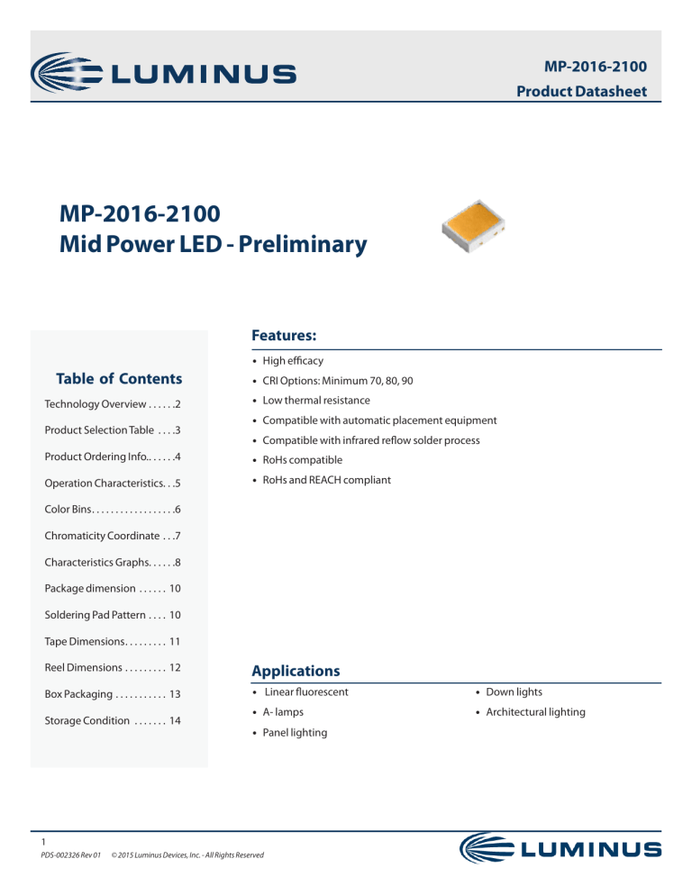
Mid Power LED - Preliminary
Features:
• High efficacy
Table of Contents
Technology Overview. . . . . . 2
Product Selection Table . . . . 3
• CRI Options: Minimum 70, 80, 90
• Low thermal resistance
• Compatible with automatic placement equipment
• Compatible with infrared reflow solder process
Product Ordering Info.. . . . . . 4
• RoHs compatible
Operation Characteristics. . .5
• RoHs and REACH compliant
Color Bins. . . . . . . . . . . . . . . . . . 6
Chromaticity Coordinate. . . 7
Characteristics Graphs. . . . . .8
Package dimension . . . . . . . 10
Soldering Pad Pattern. . . . . 10
Tape Dimensions. . . . . . . . . . 11
Reel Dimensions. . . . . . . . . . 12
Applications
Box Packaging . . . . . . . . . . . . 13
• Linear fluorescent
• Down lights
• A- lamps
• Architectural lighting
Storage Condition . . . . . . . . 14
• Panel lighting
1
PDS-002326 Rev 01
© 2015 Luminus Devices, Inc. - All Rights Reserved
MP-2016-2100
Product Datasheet
Technology Overview
Luminus mid power LEDs are lighting class solutions designed for high performance general lighting applications. These state-of-the-art
LEDs allow illumination engineers and designers to develop lighting solutions with maximum efficacy, brightness and overall quality.
Reliability
REACH & RoHS Compliance
Luminus mid power LED is one of the most reliable light sources
in the world today. Having passed a rigorous suite of
environmental and mechanical stress tests, including
mechanical shock, vibration, temperature cycling and humidity,
it is fully qualified for use in a wide range of high performance
and high efficacy lighting applications.
The Luminus 2016 mid power LED is compliant to the
Restriction of Hazardous Substances Directive or RoHS. The
restricted materials including lead, mercury cadmium,
hexavalent chromium, polybrominated biphenyls (PBB) and
polybrominated diphenyl ether (PBDE) are not used.
Understanding Luminus Mid Power LED Test Specifications
Every Luminus LED is fully tested to ensure it meets the high quality standards customers have come to expect from Luminus products.
Testing Temperature
Luminus Mid Power products are measured at a case temperature of 25°C and placed into intensity, chromaticity and voltage bins as
described herein
2
PDS-002326 Rev 01
© 2015 Luminus Devices, Inc. - All Rights Reserved
MP-2016-2100
Product Datasheet
Product Selection Table
Test condition = 60 mA, Tc=25 ºC
Nominal CCT
Minimum CRI
Ordering Part Number
Minimum Flux
(Lumens)
Typical Flux
(Lumens)
2200K
80
MP-2016-2100-22-80
36
38
80
MP-2016-2100-27-80
42
46
90
MP-2016-2100-27-90
38
42
80
MP-2016-2100-30-80
46
49
90
MP-2016-2100-30-90
42
45
80
MP-2016-2100-35-80
46
50
90
MP-2016-2100-35-90
42
46
70
MP-2016-2100-40-70
50
54
80
MP-2016-2100-40-80
46
50
90
MP-2016-2100-40-90
42
46
70
MP-2016-2100-50-70
50
54
80
MP-2016-2100-50-80
46
50
90
MP-2016-2100-50-90
42
46
70
MP-2016-2100-57-70
50
54
80
MP-2016-2100-57-80
46
50
70
MP-2016-2100-65-70
50
54
80
MP-2016-2100-65-80
46
50
2700K
3000K
3500K
4000K
5000K
5700K
6500K
*Tolerance of measurements of the luminous flux is ±7%
* Tolerance of measurements of the CRI is ±2
*IFP condition with Pulse: Width ≤100μs Duty cycle ≤1/10
3
PDS-002326 Rev 01
© 2015 Luminus Devices, Inc. - All Rights Reserved
MP-2016-2100
Product Datasheet
Product Ordering and Shipping Part Number Nomenclature
All mid power products are packaged and labeled with part numbers as outlined in below. When shipped, each reel will contain only a
single flux and voltage bin. The part number designation is as follows:
2016 Mid Power LEDs
Mid Power
Package
Type
Package
Configurator
Nominal CCT
Minimum CRI
MP
2016
2100
##
##
Example :
The part number MP-2016-2100-30-80 refers to a 2016 mid power emitter with nominal color tempecture of 3,000k and minimum CRI of 80. Please refer to
page 5 for a description of available CCT and CRI combinations.
Note 1:
CCT Codes:
Note 2:
27 = 2700 k
CRI Codes:
70
30= 3000 k
80
35= 3500 k
90
40 = 4000 k
50 = 5000 k
57= 5700 k
65 = 6500 k
Each mid power product shipped will be labeled with its specific flux and voltage bins. Not all bins listed are available in all CCTs and CRIs.
Luminus Flux Bins
Bin Code
Minimum Flux (Lumens)
Maximum Flux (Lumens)
E2
36
38
E3
38
42
E4
42
46
E5
46
50
E6
50
54
E7
54
58
E8
58
62
E9
62
66
Forward Voltage Bins (Tc=25°C)
Bin Code
Minimum Voltage (Volts)
Maximum Voltage ( Volts)
D
5.8
6.1
E
6.1
6.4
* Tolerance of measurements f the Forward Voltage is ±0.08V
4
PDS-002326 Rev 01
© 2015 Luminus Devices, Inc. - All Rights Reserved
MP-2016-2100
Product Datasheet
2016 Mid Power Operating Characteristics
Optical and Electrical Characteristics(Tc=250C)
Parameter
Symbol
Forward Voltage
Vf
Reverse Current
Ir
View Angle
2θ
Thermal Resistance
Rthj-sp
Electrostatic Discharge
ESD
Minimum
Typical
Maximum
Unit
Condition
5.8
6.1
6.4
V
If=60mA
10
uA
Vr=5V
110
º
If=60mA
27
ºC/W
If=60mA
1/2
1000
V
Note 1:
To prevent damage refer to operating conditions and derating curves for appropriate maximum operating conditions
Note 2:
Maximum operating case temperature combined with maximum drive current defines the total maximum operating condition for the device. To
prevent damage, please follow derating curves for all operating conditions.
Note 3:
Mid power LEDs are designed for operation up to an absolute maximum forward drive current as specified above. Product lifetime data is specified at
typical forward drive currents. Sustained operation at absolute maximum currents will result in a reduction of device lifetime compared to typical
forward drive currents. Actual device lifetimes will also depend on case temperature. Refer to the current vs. case temperature derating curves for
further information.
Note 4:
Caution must be taken not to stare at the light emitted from these LEDs. Under special circumstances, the high intensity could damage the eye.
Absolute Maximum Ratings (Tc=250C)
Parameter
Symbol
Rating
Unit
Forward Current
If
120
mA
Pulse Forward Current
Ifp
200
mA
Power Dissipation
Pd
768
mW
Reverse Voltage
Vr
5
V
Operating Temperature
Topr
-40~+85
°C
Storage Temperature
Tstg
-40~+85
°C
Junction Temperature
Tj
125
°C
Soldering Temperature
Tsld
230 °C or 260 °C for 10 sec
*IFP condition with Pulse: Width ≤100μs Duty cycle ≤1/10
5
PDS-002326 Rev 01
© 2015 Luminus Devices, Inc. - All Rights Reserved
MP-2016-2100
Product Datasheet
Color Bins
Color Code
Center
x
Radius
y
a
b
Angle(deg)
ϕ
22m5
0.5018
0.4152
0.013500
0.00700
59.90
27m5
0.4582
0.4099
0.013500
0.00700
53.42
30m5
0.4342
0.4028
0.013900
0.00680
53.22
35m5
0.4073
0.3917
0.01545
0.00690
53.13
40m5
0.3825
0.3789
0.015650
0.00670
53.43
50m5
0.3451
0.3554
0.013700
0.00590
59.37
57m7
0.3290
0.3417
0.015645
0.00770
58.35
65m7
0.3130
0.3290
0.015610
0.006650
58.34
Ellipse Definition
*Note: Tolerance of measurements of the chromaticity Coordinate is ±0.005
Chromaticity coordinates as per ANSI standard.
6
PDS-002326 Rev 01
© 2015 Luminus Devices, Inc. - All Rights Reserved
MP-2016-2100
Product Datasheet
Chromaticity Coordinate Group
Chromaticity Coordinates
at Tc= 85° C
7
PDS-002326 Rev 01
© 2015 Luminus Devices, Inc. - All Rights Reserved
MP-2016-2100
Product Datasheet
Typical optical/Electrical Characteristics Graphs
If---- Relative Luminous flux
Forward Current (mA)
Relative Luminous Flux %
Vf-------If
4.8
5.2
5.6
6.0
Forward Voltage (V)
6.4
6.8
Forward Current (mA)
Relative Luminous Flux %
Tc (0C)
8
PDS-002326 Rev 01
Wavelength- Relative Emission Intensity
Relative Emission Intensity %
Tc-----Relative Luminous Flux
© 2015 Luminus Devices, Inc. - All Rights Reserved
Wavelength(nm)
2016Mid Power Product Datasheet
Typical Optical/Electrical Characteristics
Ambient Temperature-Allowable Forward Current
Allowable Forward Current(mA)
Typical Polar Radiation Pattern
Ambient Temperature (0C)
Tc--Forward Voltage
Forward Current --Chromaticity Coordinate
0.409
6.6
IF=60mA
0.407
6.2
25℃
0.405
45℃
6.0
Y
Forward Voltage (V)
6.4
0.403
65℃
5.8
0.401
85℃
5.6
0.399
5.4
5.2
Tc (0C)
9
PDS-002326 Rev 01
© 2015 Luminus Devices, Inc. - All Rights Reserved
0.397
0.425
0.43
0.435
0.44
X
0.445
0.45
MP-2016-2100
Product Datasheet
Package Dimension (mm)
anode
cathode
Recommended Soldering Pad Pattern and Stencil
Soldering Pad Pattern
Note: tolerance : .X: ±0.10mm .XX: ±0.05mm
10
PDS-002326 Rev 01
© 2015 Luminus Devices, Inc. - All Rights Reserved
Stencil
MP-2016-2100
Product Datasheet
Package Dimensions Of Tape(mm)
User feed direction
cathode
Start
End
Not less than 400mm spaces
Leader
11
PDS-002326 Rev 01
© 2015 Luminus Devices, Inc. - All Rights Reserved
anode
Capacity per reel
(5000 PCs LEDs)
Not less than 160mm spaces
End
MP-2016-2100
Product Datasheet
Package Dimensions of Reel (mm)
User feed direction
Upper Band
Carrier tape
0165.1mm(6.5 inch)
013 mm
Package Dimensions of Reel (mm)
Label: contains the type, Lot #,
Quality, Product parameters
Desiccant (bag)
Humidity Card (bag)
Label: contains the type, Lot #,
Quality, Product parameters
12
PDS-002326 Rev 01
© 2015 Luminus Devices, Inc. - All Rights Reserved
Vacuum sealed
antistatic bag
MP-2016-2100
Product Datasheet
Box Packaging Information
Label: contains the type,
Lot #, Quality, Product
parameters
*Capacity 5 reels per box
Label: contains the type,
Lot #, Quality, Product
parameters
*Capacity 10 reels per box
13
PDS-002326 Rev 01
© 2015 Luminus Devices, Inc. - All Rights Reserved
MP-2016-2100
Product Datasheet
Precaution for Use
Storage:
1. This device is rated at MSL 3 per JEDEC J-STD-020 standard.
2. Recommended storage condition:
At 5 °C- 30 °C and relative humidity 60% RH in its original package
3. After this bag is opened, devices that will be applied to infrared reflow, vapor - phase reflow, or equivalent soldering process must
be:
a) Completed within 168 hours
b) Stored at less than 60%RH
c) If not completely used within 168 hours, seal the remaining in the moisture barrier bag
4. Devices require baking before mounting, if 3 a) is not met.
5. If baking is required, devices must be baked under below conditions:
24 hours at 60C+/-5C
Static Electricity:
1. The products are sensitive to static electricity, and care should be taken when handling them.
2. Static electricity or surge voltage will damage the LEDs. It is recommended to wear a anti-electrostatic wristband or an anti-electrostatic gloves when handling the LEDs.
3. All devices, equipment and machinery must be properly grounded. It is recommended that measures be taken against surge voltage to the equipment that mounts the LEDs.
14
PDS-002326 Rev 01
© 2015 Luminus Devices, Inc. - All Rights Reserved

