SST-10-IR Product Datasheet
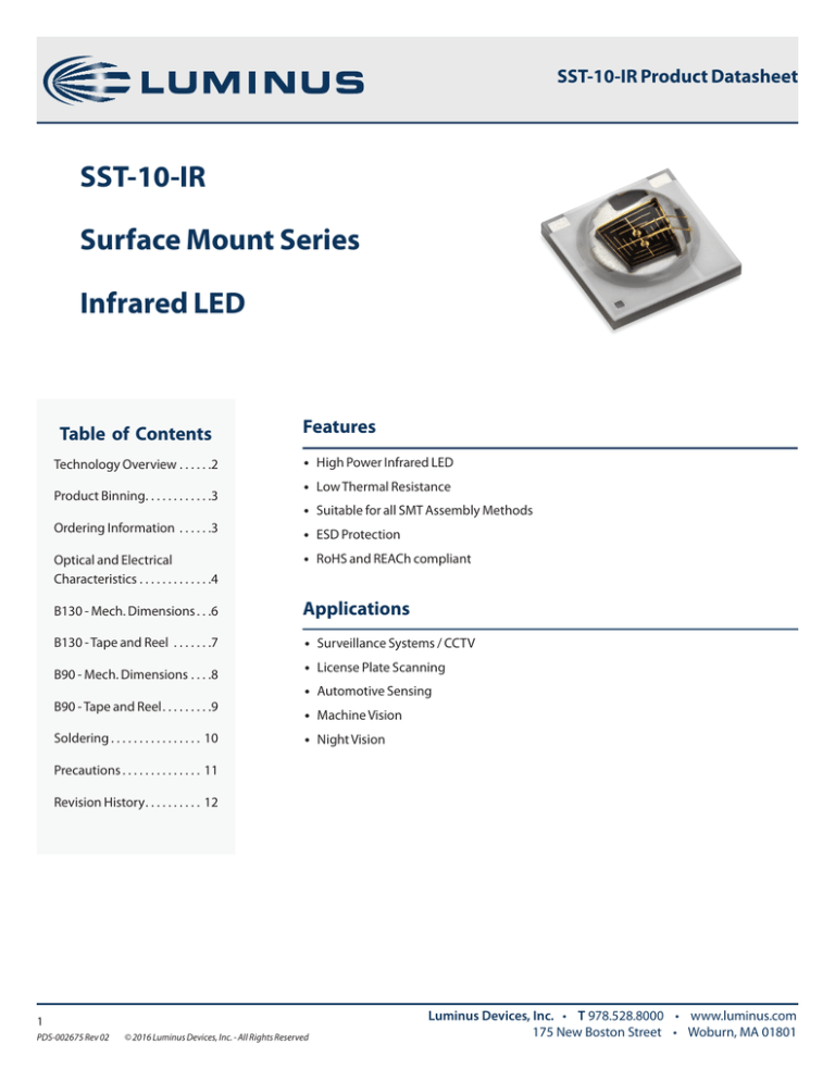
SST-10-IR
Surface Mount Series
Infrared LED
Table of Contents
Technology Overview. . . . . . 2
Product Binning. . . . . . . . . . . . 3
Features
• High Power Infrared LED
• Low Thermal Resistance
• Suitable for all SMT Assembly Methods
Ordering Information . . . . . . 3
• ESD Protection
Optical and Electrical
Characteristics. . . . . . . . . . . . . 4
• RoHS and REACh compliant
B130 - Mech. Dimensions. . . 6
Applications
B130 - Tape and Reel . . . . . . . 7
• Surveillance Systems / CCTV
B90 - Mech. Dimensions. . . . 8
B90 - Tape and Reel. . . . . . . . . 9
Soldering. . . . . . . . . . . . . . . . . 10
• License Plate Scanning
• Automotive Sensing
• Machine Vision
• Night Vision
Precautions. . . . . . . . . . . . . . . 11
Revision History. . . . . . . . . . . 12
1
PDS-002675 Rev 02
© 2016 Luminus Devices, Inc. - All Rights Reserved
Luminus Devices, Inc. • T 978.528.8000 • www.luminus.com
175 New Boston Street • Woburn, MA 01801
SST-10-IR Product Datasheet
Technology Overview
Luminus SST-10-IR LEDs benefit from innovations in device technology, chip packaging and thermal management. This suite of
technologies give engineers and system designers the freedom to develop solutions both high in power and efficiency.
Reliability
REACh & RoHS Compliance
Luminus SST-10-IR LEDs hav passed a rigorous suite of
environmental and mechanical stress tests, including
mechanical shock, vibration, temperature cycling and humidity.
They are fully qualified for use in a wide range of high
performance and high efficacy applications.
The Luminus SST-10-IR LED is compliant to the Restriction of
Hazardous Substances Directive or RoHS. The restricted
materials including lead, mercury cadmium hexavalent
chromium, polybrominated biphenyls (PBB) and
polybrominated diphenyl ether (PBDE) are not used.
Understanding Luminus SST-10-IR LED Test Specifications
Every Luminus LED is fully tested to ensure it meets the high quality standards customers have come to expect from Luminus products.
Testing Temperature
Luminus SST-10-IR LEDs are tested and binned at 25ºC junction temperature. Temperature curves are provide to allow users to scale the
data for actual operating temperature conditions.
2
PDS-002675 Rev 02
© 2016 Luminus Devices, Inc. - All Rights Reserved
Luminus Devices, Inc. • T 978.528.8000 • www.luminus.com
175 New Boston Street • Woburn, MA 01801
SST-10-IR Product Datasheet
Product Ordering and Shipping Part Number Nomenclature
All SST-10-IR products are packaged and labeled with part numbers as outlined in below. When shipped, each reel will contain only a
single flux wavelength and Vf bin. The part number designation is as follows:
Products
Ordering Part Number
SST-10-IR
Description
SST-10-IR-B###-F###-00
SST 10
Product Family
Chip Area
SST - Ceramic
Surface Mount
package w/
encapsulation
10: 1 mm
SST-10 surface mount infrared LED
CC
2
B###
F###-00
Color
Package Configuration
Bin Kit 1,2
IR = Infrared
B130 - 130deg Beam Angle
B90 - 90 deg Beam Angle
Ceramic 3.45mm x 3.45mm
See Pages 6-7 for Detailed Drawings
See below for flux
and wavelength
binning information
Peak Wavelength
Minimum Flux Bin
(mw)
Lens Angle
Ordering
Part Number
850
265
130
SST-10-IR-B130-K850-00
850
265
90
SST-10-IR-B90-K850-00
940
205
130
SST-10-IR-B130-H940-00
940
205
90
SST-10-IR-B90-H940-00
Flux Bins1
Bin Code
Minimum Flux (mw)
Maximum Flux (mw)
H
205
235
J
235
265
K
265
295
L
295
325
Bin Code
Minimum Peak Wavelength (nm)
Maximum Peak Wavelength (nm)
850
840
870
940
925
955
Wavelength Bins1
3
PDS-002675 Rev 02
© 2016 Luminus Devices, Inc. - All Rights Reserved
Luminus Devices, Inc. • T 978.528.8000 • www.luminus.com
175 New Boston Street • Woburn, MA 01801
SST-10-IR
Product
Datasheet
(Part
#) Product
Datasheet
Optical and Electrical Characteristics
Optical and Electrical Characteristics1
Parameter
Symbol
Package Type
Unit
B130-850
B90-850
B130-940
B90-940
If
350
350
350
350
mA
Output Power Typical
PO
280
280
225
225
mw
Min Voltage1
Vf min
1.2
1.2
1.2
1.2
V
Vf
1.5
1.5
1.4
1.4
V
Max Voltage1
Vf max
2.0
2.0
2.0
2.0
V
Viewing Angle
2 Ø1/2
130
90
130
90
deg
λP
850
850
940
940
nm
Δλ1/2
30
30
30
30
nm
RTH
5.3
5.3
5.3
5.3
°C/W
Forward Current
Forward Voltage Typical
Peak Wavelength Typical
FWHM Typical
Thermal Resistance (Electrical)
Absolute Maximum Ratings2
Parameter
Symbol
Rating
Unit
Forward Current
I
1.5
A
Power Dissipation
Pd
3.0
W
Reverse Voltage
Vr
5
V
Storage Temperature
Tstg
-40~100
°C
Junction Temperature3,4
Tj
115 ºC
°C
Soldering Temperature
Tsld
JEDEC 020 , 260 ºC
ESD Sensitivity (HBM)
Vb
6000
3,4
V
Note 1: Binning based on operation at a current of 350mA and a constant junction temperature of Tj = 25ºC. Parts are binned and shipped in 0.2V Vf
increments.
Note 2: To prevent damage refer to operating conditions and derating curves for appropriate maximum operating conditions
Note 3: Luminus SST-10-IR LEDs are designed for operation up to an absolute maximum forward drive current as specified above. Product lifetime data is
specified at typical forward drive currents. Sustained operation at absolute maximum currents will result in a reduction of device lifetime compared
to typical forward drive currents. Actual device lifetimes will also depend on junction temperature.
Note 4: Maximum operating case temperature combined with maximum drive current defines the total maximum operating condition for the device. To
prevent damage, please operate devices within specified conditions.
Note 5: Caution must be taken not to stare at the light emitted from these LEDs. Under special circumstances, the high intensity could damage the eye.
4
PDS-002675 Rev 02
© 2016 Luminus Devices, Inc. - All Rights Reserved
Luminus Devices, Inc. • T 978.528.8000 • www.luminus.com
175 New Boston Street • Woburn, MA 01801
SST-10-IR
Product
Datasheet
(Part
#) Product
Datasheet
Optical and Electrical Characteristics
Relative Output Flux vs. Forward Current
Relative Voltage vs Forward Current
Relative Output Flux vs. Temperature
Typical Spectra
Typical Polar Radiation Plot - B130
Typical Polar Radiation Plot - B90
20°
10°
0°
20°
1.0
30°
40°
40°
0.8
0.8
50°
0.6
60°
0.8
0.6
0.4
0.2
0
0.2
80°
20°
40°
5
PDS-002675 Rev 02
0.4
70°
0.2
80°
0.6
60°
0.4
70°
1.0
0°
1.0
30°
50°
90°
10°
© 2016 Luminus Devices, Inc. - All Rights Reserved
60°
80°
90°
1.0
0.8
0.6
0.4
0.2
0
20°
40°
60°
80°
Luminus Devices, Inc. • T 978.528.8000 • www.luminus.com
175 New Boston Street • Woburn, MA 01801
SST-10-IR Product Datasheet
Mechanical Dimensions - B130 Package
2.23
.088
A
1.38
.054
1.38
.054
E
CENTER OF DIE EMITTING AREA
.15[.006] M A B
CENTER OF ZENER DIODE
.30[.012] M A B
.70±.13
.028±.005
BACK OF SUBSTRATE
TO TOP OF DIE
EMITTING AREA
B
R.2
.006
2.60
.102
1.18
.046
2.7
.106
.38
.015
ANODE
.20
3.45+.00
+.008
.136 - .000
1.0
.039
THERMAL PAD
(NEUTRAL)
1.7
.067
2.7
.106
CATHODE
E
1.0
.041
DIE EMITTING AREA
1.0
.041
DIE EMITTING
AREA
.20
3.45+.00
+.008
.136 - .000
.60±.13
.023±.005
1.90±.13
.075±.005
SECTION E-E
2.7
.106
R.2
.008
1.0
.039
1.7
.067
2.7
.106
RECOMMENDED SOLDER PAD LAYOUT
6
PDS-002675 Rev 02
© 2016 Luminus Devices, Inc. - All Rights Reserved
Luminus Devices, Inc. • T 978.528.8000 • www.luminus.com
175 New Boston Street • Woburn, MA 01801
SST-10-IR Product Datasheet
Tape and Reel - B130 Package
$
&$7+2'(6,'(
%
%
815((/,1*',5(&7,21
$12'(6,'(
$
6(&7,21%%
6(&7,21$$
127(6
),1$/7$3($1'5((/3$&.$*,1*08670((77+(
5(48,5(0(1762)-('(&67'/(9(/$
/($9(PP>LQ@2)7$3((037<)25/($',1
(037<32&.(76
/($9(PP>LQ@2)7$3((037<)2575$,/(5
(037<32&.(76
0867&203/<72(,$&
;
&
'(7$,/&
815((/,1*',5(&7,21
7239,(:
'(7$,/'
7
PDS-002675 Rev 02
© 2016 Luminus Devices, Inc. - All Rights Reserved
Luminus Devices, Inc. • T 978.528.8000 • www.luminus.com
175 New Boston Street • Woburn, MA 01801
SST-10-IR Product Datasheet
Mechanical Dimensions - B90 Package
2.23
.088
A
1.38
.054
E
.70±.13
.028±.005
BACK OF SUBSTRATE
TO TOP OF DIE
EMITTING AREA
B
CENTER OF ZENER DIODE
.30[.012] M A B
2.15
.085
1.18
.046
1.38
.054
CENTER OF DIE EMITTING AREA
.15[.006] M A B
R.2
.008
2.7
.106
.38
.015
ANODE
.20
3.45+.00
+.008
.136 - .000
1.0
.039
THERMAL PAD
(NEUTRAL)
1.7
.067
2.7
.106
CATHODE
E
1.0
.041
DIE EMITTING AREA
1.0
.041
DIE EMITTING
AREA
.20
3.45+.00
+.008
.136 - .000
2.33
2.09
.092
.082
SECTION E-E
.63
.025
2.7
.106
R.2
.008
1.0
.039
1.7
.067
2.7
.106
RECOMMENDED SOLDER PAD LAYOUT
8
PDS-002675 Rev 02
© 2016 Luminus Devices, Inc. - All Rights Reserved
Luminus Devices, Inc. • T 978.528.8000 • www.luminus.com
175 New Boston Street • Woburn, MA 01801
SST-10-IR Product Datasheet
Tape and Reel - B90 Package
$
$
&$7+2'(6,'(
&$7+2'(6,'(
%
%
%
%
$12'(6,'(
$12'(6,'(
$
$
6(&7,21$$
6(&7,21$$
127(6
127(6
),1$/7$3($1'5((/3$&.$*,1*08670((77+(
),1$/7$3($1'5((/3$&.$*,1*08670((77+(
5(48,5(0(1762)-('(&67'/(9(/$
5(48,5(0(1762)-('(&67'/(9(/$
/($9(PP>LQ@2)7$3((037<)25/($',1
/($9(PP>LQ@2)7$3((037<)25/($',1
(037<32&.(76
(037<32&.(76
/($9(PP>LQ@2)7$3((037<)2575$,/(5
/($9(PP>LQ@2)7$3((037<)2575$,/(5
(037<32&.(76
(037<32&.(76
0867&203/<72(,$&
0867&203/<72(,$&
6(&7,21%%
6(&7,21%%
815((/,1*',5(&7,21
815((/,1*',5(&7,21
;
&
'(7$,/&
815((/,1*',5(&7,21
815((/,1*',5(&7,21
7239,(:
7239,(:
'(7$,/'
'(7$,/'
9
PDS-002675 Rev 02
© 2016 Luminus Devices, Inc. - All Rights Reserved
Luminus Devices, Inc. • T 978.528.8000 • www.luminus.com
175 New Boston Street • Woburn, MA 01801
SST-10-IR Product Datasheet
Soldering Profile
Profile Feature
Sn-Pb Eutectic Assembly
Pb-Free Assembly
Preheat & Soak
Temperature min (Tsmin)
Temperature max (Tsmax)
Time (Tsmin to Tsmax) (ts)
100 °C
150 °C
60-120 seconds
150 °C
200 °C
60-120 seconds
Average ramp-up rate (Tsmax to Tp)
3 °C/second max
3 °C/second max
Liquidous temperature (TL)
Time at liquidous (tL)
183 °C
60-150 seconds
217 °C
60-150 seconds
Peak package body temperature (Tp)*
230 °C ~235 °C
255 °C ~260 °C
Classification temperature (Tc)
Time (tp) within 5 °C of the specified
classification temperature (Tc)
Average ramp-down rate (Tp to Tsmax)
Time 25 °C to peak temperature
235 °C
260 °C
20 seconds
30 seconds
6 °C/second max
6 °C/second max
6 minutes max
8 minutes max
* Tolerance for peak profile temperature(Tp) is defined as a supplier minimum and a user maximum.
** Tolerance for time at peak profile temperature(tp) is defined as asupplier minimum and a user maximum.
10
PDS-002675 Rev 02
© 2016 Luminus Devices, Inc. - All Rights Reserved
Luminus Devices, Inc. • T 978.528.8000 • www.luminus.com
175 New Boston Street • Woburn, MA 01801
SST-10-IR Product Datasheet
Precautions for Use
Storage:
1. Before opening the package
The LEDs should be kept at <40 & <90%RH. The LEDs should be used within a year. When storing the LEDs, moisture proof package
with absorbent material (silica gel) is recommended.
2. After opening the package
The LEDs should be kept at ≤ 30 & ≤ 60%RH. The LEDs should be soldered within 168 hours (7days) after opening the moisture proof
package.
If unused LEDs remain, they should be stored in moisture proof packages, such as sealed containers with moisture proof package
within absorbent material (silica gel).It is also recommended to return the unused LEDs to the original moisture proof package and to
seal the moisture proof package again.
If the moisture absorbent material (silica gel) vapors or expires the expiration date, baking treatment should be performed by using
the following conditions : 60 °C for 20 hours.
The LEDs electrode and leadframe comprise a silver plated copper alloy. The silver surface may be affected by environments. Please
avoid conditions which may cause the LEDs being corroded or discolored. The corrosion or discoloration might lower solderability or
affect optical characteristics.
Please avoid rapid transition in ambient temperature, especially in high humidity environments where condensation can occur.
Static Electricity:
1. The products are sensitive to static electricity, and care should be taken when handling them.
2. Static electricity or surge voltage will damage the LEDs. It is recommended to wear a anti-electrostatic wristband or an anti-electrostatic gloves when handling the LEDs.
3. All devices, equipment and machinery must be properly grounded. It is recommended that measures be taken against surge voltage to the equipment that mounts the LEDs.
11
PDS-002675 Rev 02
© 2016 Luminus Devices, Inc. - All Rights Reserved
Luminus Devices, Inc. • T 978.528.8000 • www.luminus.com
175 New Boston Street • Woburn, MA 01801
SST-10-IR Product Datasheet
History of Changes
Rev
Date
Description of Change
01
01/13/2016
Initial Release
02
03/28/2016
Updated Binning and Angular Distribution Data, Addded 90deg Tape and Reel
The products, their specifications and other information appearing in this document are subject to change by Luminus Devices without notice. Luminus
Devices assumes no liability for errors that may appear in this document, and no liability otherwise arising from the application or use of the product or
information contained herein. None of the information provided herein should be considered to be a representation of the fitness or suitability of the
product for any particular application or as any other form of warranty. Luminus Devices’ product warranties are limited to only such warranties as
accompany a purchase contract or purchase order for such products. Nothing herein is to be construed as constituting an additional warranty. No
information contained in this publication may be considered as a waiver by Luminus Devices of any intellectual property rights that Luminus Devices
may have in such information. Big Chip LEDs™ is a registered trademark of Luminus Devices, Inc., all rights reserved.
This product is protected by U.S. Patents 6,831,302; 7,074,631; 7,083,993; 7,084,434; 7,098,589; 7,105,861; 7,138,666; 7,166,870; 7,166,871; 7,170,100;
7,196,354; 7,211,831; 7,262,550; 7,274,043; 7,301,271; 7,341,880; 7,344,903; 7,345,416; 7,348,603; 7,388,233; 7,391,059 Patents Pending in the U.S. and
other countries.
12
PDS-002675 Rev 02
© 2016 Luminus Devices, Inc. - All Rights Reserved
Luminus Devices, Inc. • T 978.528.8000 • www.luminus.com
175 New Boston Street • Woburn, MA 01801

