Fluorescent Screen Assembly FC-204
advertisement
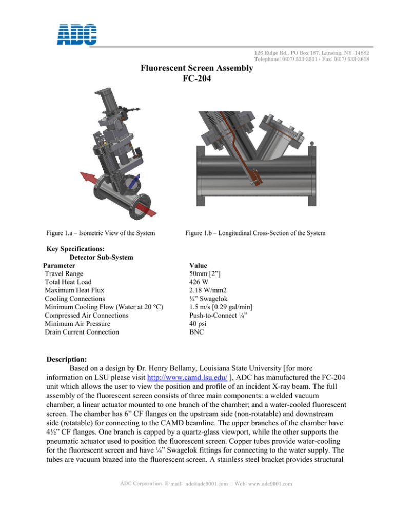
126 Ridge Rd., PO Box 187, Lansing, NY 14882 Telephone: (607) 533-3531 Fax: (607) 533-3618 Fluorescent Screen Assembly FC-204 Figure 1.a – Isometric View of the System Key Specifications: Detector Sub-System Parameter Travel Range Total Heat Load Maximum Heat Flux Cooling Connections Minimum Cooling Flow (Water at 20 °C) Compressed Air Connections Minimum Air Pressure Drain Current Connection Figure 1.b – Longitudinal Cross-Section of the System Value 50mm [2”] 426 W 2.18 W/mm2 ¼” Swagelok 1.5 m/s [0.29 gal/min] Push-to-Connect ¼” 40 psi BNC Description: Based on a design by Dr. Henry Bellamy, Louisiana State University [for more information on LSU please visit http://www.camd.lsu.edu/ ], ADC has manufactured the FC-204 unit which allows the user to view the position and profile of an incident X-ray beam. The full assembly of the fluorescent screen consists of three main components: a welded vacuum chamber; a linear actuator mounted to one branch of the chamber; and a water-cooled fluorescent screen. The chamber has 6” CF flanges on the upstream side (non-rotatable) and downstream side (rotatable) for connecting to the CAMD beamline. The upper branches of the chamber have 4½” CF flanges. One branch is capped by a quartz-glass viewport, while the other supports the pneumatic actuator used to position the fluorescent screen. Copper tubes provide water-cooling for the fluorescent screen and have ¼” Swagelok fittings for connecting to the water supply. The tubes are vacuum brazed into the fluorescent screen. A stainless steel bracket provides structural ADC Corporation. E- 126 Ridge Rd., PO Box 187, Lansing, NY 14882 Telephone: (607) 533-3531 Fax: (607) 533-3618 support for the screen and cooling tubes. The screen itself is at a 60° angle from the horizontal plane. The face of the screen is coated with P22R phosphor and features equally spaced grooves cut into the surface for imaging from the viewport above. The lower hard stop for the pneumatic actuator allows the screen location to be fine-tuned as needed to place the beam on a flat or a groove in the grid. Inventor Simulation was used to perform steady-state thermal analysis on the fluorescent screen assembly. An average mesh size of 0.6 mm was used for each analysis. A surface heat flux of 2.18 W/mm2 was applied over the 40 mm x 5 mm beam footprint centered on the fluorescent face. Figure 2 below shows the model used in the simulations, while Fig. 3 shows results of the simulation. Figure 2 – Model of screen used in simulations Figure 3 – Simulation Results ADC Corporation. E-
