20 Milliamp Signals
advertisement
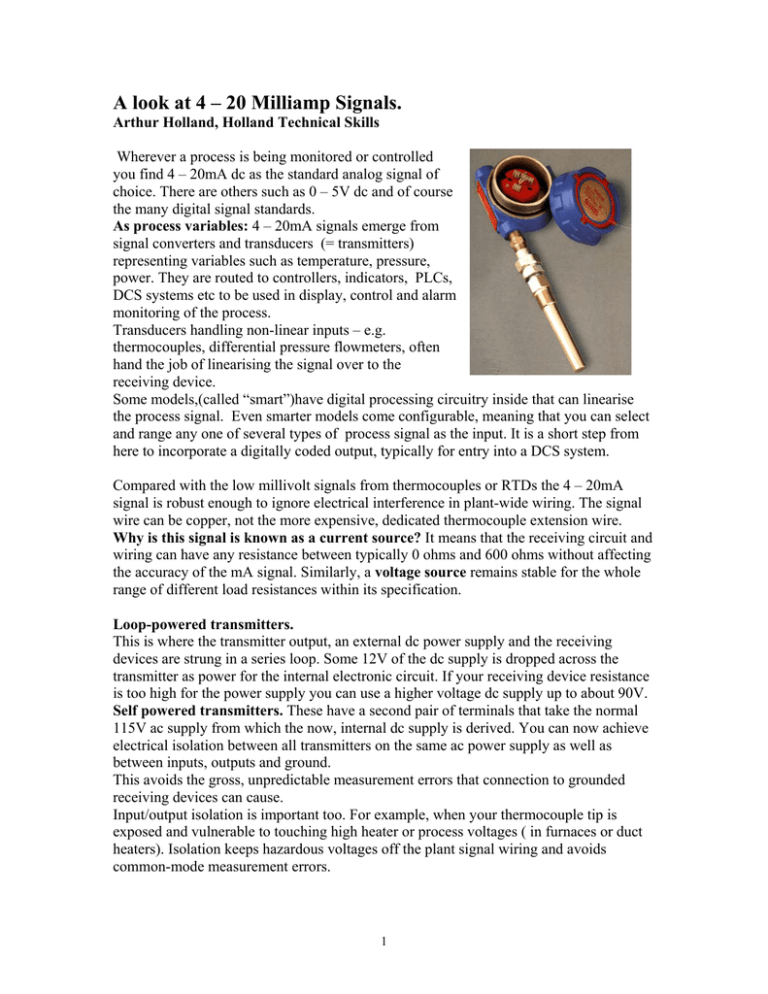
A look at 4 – 20 Milliamp Signals. Arthur Holland, Holland Technical Skills Wherever a process is being monitored or controlled you find 4 – 20mA dc as the standard analog signal of choice. There are others such as 0 – 5V dc and of course the many digital signal standards. As process variables: 4 – 20mA signals emerge from signal converters and transducers (= transmitters) representing variables such as temperature, pressure, power. They are routed to controllers, indicators, PLCs, DCS systems etc to be used in display, control and alarm monitoring of the process. Transducers handling non-linear inputs – e.g. thermocouples, differential pressure flowmeters, often hand the job of linearising the signal over to the receiving device. Some models,(called “smart”)have digital processing circuitry inside that can linearise the process signal. Even smarter models come configurable, meaning that you can select and range any one of several types of process signal as the input. It is a short step from here to incorporate a digitally coded output, typically for entry into a DCS system. Compared with the low millivolt signals from thermocouples or RTDs the 4 – 20mA signal is robust enough to ignore electrical interference in plant-wide wiring. The signal wire can be copper, not the more expensive, dedicated thermocouple extension wire. Why is this signal is known as a current source? It means that the receiving circuit and wiring can have any resistance between typically 0 ohms and 600 ohms without affecting the accuracy of the mA signal. Similarly, a voltage source remains stable for the whole range of different load resistances within its specification. Loop-powered transmitters. This is where the transmitter output, an external dc power supply and the receiving devices are strung in a series loop. Some 12V of the dc supply is dropped across the transmitter as power for the internal electronic circuit. If your receiving device resistance is too high for the power supply you can use a higher voltage dc supply up to about 90V. Self powered transmitters. These have a second pair of terminals that take the normal 115V ac supply from which the now, internal dc supply is derived. You can now achieve electrical isolation between all transmitters on the same ac power supply as well as between inputs, outputs and ground. This avoids the gross, unpredictable measurement errors that connection to grounded receiving devices can cause. Input/output isolation is important too. For example, when your thermocouple tip is exposed and vulnerable to touching high heater or process voltages ( in furnaces or duct heaters). Isolation keeps hazardous voltages off the plant signal wiring and avoids common-mode measurement errors. 1 As a control signal the 4 – 20mA would come from say the output of a temperature controller and feed into a final control device such as an electro-pneumatic control valve or silicon controlled rectifier . Usually a high control signal calls for high output of your final control device (direct acting mode). Reverse acting is the other option, e.g. high milliamps to close your valve. So pause and decide which action you want. If your controller or wiring should break with loss of milliamps, choose the mode that you reckon is fail-safe. Force-balance principle: The 4 – 20mA signal is about the right size for use in the force balance system found in pressure transmitters. Here the magnetic force of the milliamps in a coil performs a null-balance against the diaphragm pressure, resulting in an accurate transduction of pressure to milliamps. The same principle is used in I/P (current to pressure) converters, often incorporated into electro-pneumatic control valves; also in valve positioners where, by servo action the valve is forced to a position proportional to the mA signal. Signal converters. A simple example is the signal isolator with 4 – 20mA in and 4 – 20mA out. It is used to isolate an incoming signal that is grounded, from a receiving device that cannot tolerate a second ground reference. The input/output/ground isolation will usually withstand about 1500V. There are many combinations of available signal ranges for both inputs and outputs including multiple channels, mathematical functions, user defined linearisations. Packaging can be a DIN rail mounted box or a plant mounted pillbox shaped enclosure with two pairs of terminals, input and output. A third pair is added on models having external ac power. 4-20mA.doc 2001/April/26Arthur Holland. Holland Technical Skills. Ph: 905 827 5650 email: 2 aholland51@cogeco.ca
