III.Specification
advertisement
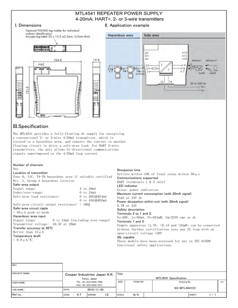
MTL4541 REPEATER POWER SUPPLY 4-20mA, HART®, 2- or 3-wire transmitters II. Application example I. Dimensions III.Specification The MTL4541 provides a fully-floating dc supply for energising a conventional 2- or 3-wire 4/20mA transmitter, which is located in a hazardous area, and repeats the current in another floating circuit to drive a safe-area load. For HART 2-wire transmitters, the unit allows bi-directional communications signals superimposed on the 4/20mA loop current. Number of channels One Location of transmitter Zone 0, IIC, T4-T6 hazardous area if Div. 1, Group A hazardous location Safe-area output Signal range: Under/over-range: Safe-area load resistance: suitably certified 4 to 20mA 0 to 24mA 0 to 360Ω@24mA 0 to 450Ω@20mA Safe-area circuit output resistance: > 1MΩ Safe-area circuit ripple < 50μA peak-to-peak Hazardous-area input Signal range: 0 to 24mA (including over-range) Transmitter voltage: 16.5V at 20mA Transfer accuracy at 20℃ Better than 15μA Temperature draft < 0.8μA/℃ Rresponse time Settles within 10% of final value within 50μs Communications supported HART (terminals 1 & 2 only) LED indicator Green: power indication Maximum current consumption (with 20mA signal) 51mA at 24V dc Power dissipation within unit (with 20mA signal) 0.7W at 24V Safety description Terminals 2 to 1 and 3: Vo=28V, Io=93mA, Po=651mW, Um=253V rms or dc Terminals 1 and 3: Simple apparatus <1.5V, <0.1A and <25mW; can be connected without further certification into any IS loop with an open-circuit voltage <28V SIL capable These models have been assessed for use in IEC 61508 functional safety applications. REV. PROJECT NAME: Cooper Industries Japan K.K. Title MTL4541 Specification Tokyo, Japan SIZE TEL: +81-(0)3-6434-7890 FAX: +81-(0)3-6434-7871 USER NAME : JOB NAME: DATE: Ref no.: CHKD FSCM NO DRAWN rev SS-MTL4541(E) 2010/11/29 K.T Drawing No. I.S SCALE N/A SHEET 1/1
