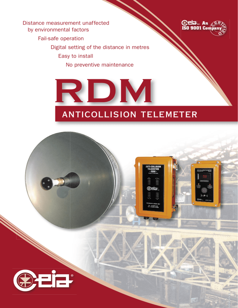
anticollision telemeter

Distance measurement unaffected
by environmental factors
Fail-safe operation
Digital setting of the distance in metres
Easy to install
No preventive maintenance
RDM
anticollision telemeter
CEIA RDM - Anticollision Telemeter
C EIA anticollision telemeters are operator-support protective devices for bridge cranes travelling along the same running plane, in compliance with the safety regulations foreseen under D.P.R. N° 547, D.Lgs. N° 626 and Machinery Directive 98/37/CE (D.P.R. N° 459).
Operation of RDM telemeters is based on the emission of a highlydirectional electromagnetic fi eld , provided by a transmitter, so as to obtain the distance from the adjacent bridge crane via the signal refl ected from the latter, and thus trigger intervention by the slowing and stopping relays. The intervention thresholds, expressed in metres, can be pre-set digitally. Two additional thresholds can be provided on request.
Thanks to application of the principle
FM-CW Radar
, the CEIA anticollision telemeter provides
A cabin repeater equipped with a luminous display and acoustic signalling device tells the operator the distance in metres from the adjacent bridge crane and gives information on slowing and stopping operations, allowing realtime assessment of the approach speed.
precise, repetitive measurements , even under the most diffi cult environmental conditions, and operates in Fail-safe mode, thus affording maximum protection for the operators and structures
The CEIA RDM telemeter is a variant of the altimetric radar system (Pat. CEIA N° 1244/
B/83): the accuracy of the measurement obtained is independent of both environmental and electrical operating conditions . This measurement, being based on the calculation of the return time of the electromagnetic wave, is insensitive to attenuations due to airborne dust, meteorological phenomena, vibrations and electromagnetic and other interference, thus guaranteeing full response. The device incorporates an autodiagnostic system that checks the parts that are essential for operation and manages the safety intervention relays (normally excited). The completely passive nature of the refl ector guarantees that the CEIA RDM anticollision telemeter operates in fail-safe mode.
The use of high-integration technology and the implementation of suitable mathematical algorithms in the microprocessor allow high performance to be achieved in terms of reliability and accuracy of measurement.
Advantages of the CEIA RDM Anticollision system
OPERATING PRINCIPLE
MAX. DISTANCE MEASUREMENT
DIGITAL SETTING OF INTERVENTION
DISTANCES
UNAFFECTED BY ENVIRONMENTAL
FACTORS
FAILSAFE OPERATION
RELATIVE VELOCITY INFORMATION
ACCURACY OF MEASUREMENT
INDEPENDENT OF VELOCITY OF THE
CRANES
AUTOMATIC CHANNELLING
(SYNCHRONISATION BETWEEN TWO
OR MORE TELEMETERS)
EASY TO INSTALL
CEIA ALTIMETRIC
RADAR
MICROWAVES
99 m
YES*
YES
YES
YES
YES
YES
YES
DOPPLER
MICROWAVES
20 ÷ 25 m
NO
NO
NO**
YES
YES
YES
INDUCTION
FIELD
20 m
NO
NO
NO
NO
NO YES
NO
NO
OPTICAL ULTRASONIC ELECTROMECHANICAL
10 ÷ 15 m
NO
NO
YES
NO
YES
YES
NO
28 m
NO
NO
YES
NO
NO
NO
NO
2 ÷ 3 m
NO
YES
_
NO
_
YES
YES
* Also programmable as a function of the speed approaching; ** Refl ector with active transponder
Product models and Confi gurations
Models
RDM/1S-20
RDM/2S-20
Control unit, models
RDM/1S-20, RDM/2S-20
202 mm
Slowing distance
_
4 ÷ 20 m
Stop distance
4 ÷ 20 m
4 ÷ 20 m
375 mm
Control unit RDM
RDM/1S-30
RDM/1S-60
RDM/2S-30
RDM/2S-60
RDM/2S-99
RDM-RC
RDM-ARU
Options
_
_
5 ÷ 30 m
5 ÷ 60 m
135 mm mod. 450
Parabola RDM
5 ÷ 30 m
5 ÷ 60 m
5 ÷ 30 m
5 ÷ 60 m mod. 450
5 ÷ 99 m 5 ÷ 99 m mod. 600
Description
Remote display unit showing distance and intervention status. Fitted with digital display, LED signalling and acoustic alarm
Expansion unit, connected to the RDM basic unit via serial cable, enabling implementation of two additional digitally-set intervention thresholds
285 mm
Refl ector RDM
A
A
A
B model
450
600
A (mm) B (mm)
450 720
600 970
Cab repeater RDM
Threshold 1 display (slowing down)
Threshold 2 display (stop)
Distance measured display
Threshold 1 intervention indicator (slowing down)
Threshold 2 intervention indicator (stop)
Terminal board
On/off switch
90 mm
www.ceia.net
Technical
Characteristics
l Intervention distances adjustable: from 4 m to 20 m (RDM/20); from 5 m to 30 m (RDM/30); from 5 m to 60 m (RDM/60); from 5 m to 99 m (RDM/99) l Digital setting of distance in metres. Measurement resolution: 1 metre, with indication independent of environmental and ageing-related factors.
l Digital indication of the distance in metres via luminous display in cabin.
l Acoustic signalling of slowing and stopping
(optional, via Mod. RDM-RC repeater).
l Directivity superior to any other system currently on the market (-3 dB at 3°).
l Minimal power density of emitted signal: 3,5µW/cm 2 in contact with the parabola.
l No danger to people or objects
(limit of Osha=1 mW/cm 2 ).
l Easy alignment of the refl ector with the transmitter, guided by LED indicators located both on the display unit and on the parabola.
l Unaffected by normal bridge-crane skew.
l Unaffected by variations in power supply voltage of +15/-20% at constant rate.
l Unaffected by sudden variations in power supply voltage due to spikes up to - 40%.
l Measurement unaffected by rising hot air currents, vibrations, humidity, rain or dust.
l Autodiagnosis of transmitter group, receiver, frequency modulator, quartz time base and power supply; any failure is signalled by dropout of the stop relay.
l No preventive maintenance.
l All operations controlled by a microcomputer.
l Anti-interference fi lter between conductors and earth for voltages up to 3 kV for 500 µs or 1500 V 50 Hz for
3 s.
l Electronics unit in IP55 container.
l Operating voltage: 220 V 50/60 Hz;
110 V 50/60 Hz on request.
l Operating temperature: -15 ÷ +70°C.
l Absorbed power: 25 VA.
l Relay current-carrying capacity: 10 A 250 Vca.
l Complies with CE and international regulations regarding electrical safety and electromagnetic compatibility (EMC).
l Unrestricted-use transceiver equipment
(ERC/REC 70-03E).
C
OSTRUZIONI
E
LETTRONICHE
I
NDUSTRIALI
A
UTOMATISMI
Zona Ind.le 54/G, 52040 Viciomaggio - AREZZO (ITALY)
Tel.: +39 0575 4181 Fax: +39 0575 418296 E-mail: qa-detectors@ceia-spa.com
www.ceia.net


