SPECIFICATIONS
NI myDAQ
Analog Input
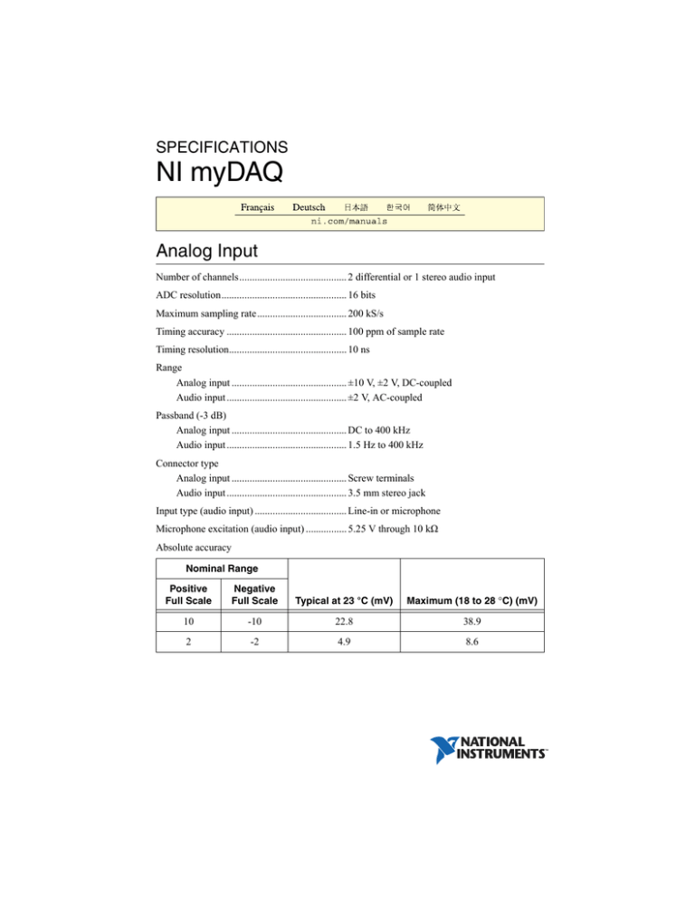
Number of channels.......................................... 2 differential or 1 stereo audio input
ADC resolution................................................. 16 bits
Maximum sampling rate ................................... 200 kS/s
Timing accuracy ............................................... 100 ppm of sample rate
Timing resolution.............................................. 10 ns
Range
Analog input ............................................. ±10 V, ±2 V, DC-coupled
Audio input ............................................... ±2 V, AC-coupled
Passband (-3 dB)
Analog input ............................................. DC to 400 kHz
Audio input ............................................... 1.5 Hz to 400 kHz
Connector type
Analog input ............................................. Screw terminals
Audio input ............................................... 3.5 mm stereo jack
Input type (audio input) .................................... Line-in or microphone
Microphone excitation (audio input) ................ 5.25 V through 10 kΩ
Absolute accuracy
Nominal Range
Positive
Full Scale
Negative
Full Scale
Typical at 23 °C (mV)
Maximum (18 to 28 °C) (mV)
10
-10
22.8
38.9
2
-2
4.9
8.6
Figure 1. Settling Time (10 V Range) versus Different Source Impedance
4
3.75
3.5
2 kΩ
5 kΩ
3.25
10 kΩ
3
2.75
Settling Error (%)
2.5
2.25
2
1.75
1.5
1.25
1
0.75
0.5
0.25
0
–0.25
200
180
160
140
120
100
Sample Rate (kHz)
80
60
40
Figure 2. Settling Time (2 V Range) versus Different Source Impedance
2.8
2.6
2 kΩ
5 kΩ
2.4
10 kΩ
2.2
Settling Error (%)
2
1.8
1.6
1.4
1.2
1
0.8
0.6
0.4
0.2
0
–0.2
200
2
|
ni.com
|
180
160
NI myDAQ specifications
100
140
120
Sample Rate (kHz)
80
60
40
Input FIFO size ................................................. 4,095 samples, shared among channels used
Maximum working voltage for analog
inputs (signal + common mode) ....................... ±10.5 V to AGND
Common-mode rejection
ratio (CMRR) (DC to 60 Hz)............................ 70 dB
Input impedance
Device on
AI+ or AI- to AGND ........................ >10 GΩ || 100 pF
AI+ to AI- ......................................... >10 GΩ || 100 pF
Device off
AI+ or AI- to AGND ........................ 5 kΩ
AI+ to AI- ......................................... 10 kΩ
Anti-aliasing filter............................................. None
Overvoltage protection
AI+ or AI - to AGND ....................................... ±16 V
Overvoltage protection
(audio input left and right)................................ None
Analog Output
Number of channels.......................................... 2 ground-referenced or 1 stereo audio output
DAC resolution................................................. 16 bits
Maximum update rate ....................................... 200 kS/s
Range
Analog output ........................................... ±10 V, ±2 V, DC-coupled
Audio output ............................................. ±2 V, AC-coupled
Maximum output current
(analog output)1 ................................................ 2 mA
Output impedance
Analog output ........................................... 1 Ω
Audio output ............................................. 120 Ω
Minimum load impedance
(audio output) ................................................... 8 Ω
1
The total power available for the power supplies, analog outputs, and digital outputs is limited to 500 mW
(typical)/100 mW (minimum). Refer to the Calculating Power Consumption section for information on
calculating the total power consumption of the components of your system.
NI myDAQ specifications
|
© National Instruments
|
3
Connector type
Analog output ...........................................Screw terminals
Audio output .............................................3.5 mm stereo jack
AC-coupling high-pass frequency
(audio output with 32 Ω load)...........................48 Hz
Absolute accuracy
Nominal Range
Positive
Full Scale
Negative
Full Scale
Typical at 23 °C (mV)
Maximum (18 to 28 °C) (mV)
10
-10
19.6
42.8
2
-2
5.4
8.8
Slew rate ...........................................................4 V/μs
Timing accuracy................................................100 ppm of sample rate
Timing resolution..............................................10 ns
Overdrive protection .........................................±16 V to AGND
Maximum power-on voltage1 ...........................±110 mV
Output FIFO size ..............................................8,191 samples, shared among channels used
Digital I/O
Number of lines ................................................8; DIO <0..7>
Direction control ...............................................Each line individually programmable as input or
output
Update mode .....................................................Software-timed
Pull-down resistor .............................................75 kΩ
Logic level ........................................................5 V compatible LVTTL input; 3.3 V LVTTL
output
VIH min .............................................................2.0 V
VIL max .............................................................0.8 V
Maximum output current per line2 ....................4 mA
1
2
4
When powered on, the analog output signal is not defined until after USB configuration is complete.
The total power available for the power supplies, analog outputs, and digital outputs is limited to 500 mW
(typical)/100 mW (minimum). Refer to the Calculating Power Consumption section for information on
calculating the total power consumption of the components of your system.
|
ni.com
|
NI myDAQ specifications
General Purpose Counter/Timer
Number of counter/timers................................. 1
Resolution......................................................... 32 bits
Internal base clocks .......................................... 100 MHz
Base clock accuracy.......................................... 100 ppm
Maximum counting and pulse
generation update rate....................................... 1 MS/s
Default routing
CTR 0 SOURCE....................................... PFI 0 routed through DIO 0
CTR 0 GATE ............................................ PFI 1 routed through DIO 1
CTR 0 AUX.............................................. PFI 2 routed through DIO 2
CTR 0 OUT .............................................. PFI 3 routed through DIO 3
FREQ OUT............................................... PFI 4 routed through DIO 4
Data transfers.................................................... Programmed I/O
Update mode..................................................... Software-timed
Digital Multimeter
Functions1 ......................................................... DC voltage, AC voltage, DC current,
AC current, resistance, diode, continuity
Isolation level ................................................... 60 VDC/20 Vrms, Measurement Category I
Caution Do not use this device for connection to signals or for measurements
within Measurement Categories II, III, or IV. For more information on Measurement
Categories, refer to the Safety Voltages section.
Connectivity...................................................... Banana jacks
Resolution ......................................................... 3.5 digits
Input coupling................................................... DC (DC Voltage, DC Current, Resistance,
Diode, Continuity);
AC (AC Voltage, AC Current)
Voltage Measurement
DC ranges ......................................................... 200 mV, 2 V, 20 V, 60 V
AC ranges ......................................................... 200 mVrms, 2 Vrms, 20 Vrms
1
All AC specifications are based on sine wave RMS.
NI myDAQ specifications
|
© National Instruments
|
5
Note All AC voltage accuracy specifications apply to signal amplitudes greater
than 5% of range.
Accuracy
Accuracy
Function
Range
Resolution
± ([% of Reading] + Offset)
DC Volts
200.0 mV
0.1 mV
0.5% + 0.2 mV
2.000 V
0.001 V
0.5% + 2 mV
20.00 V
0.01 V
0.5% + 20 mV
60.0 V
0.1 V
0.5% + 200 mV
AC Volts
40 to 400 Hz
400 to 2,000 Hz
200.0 mV
0.1 mV
1.4% + 0.6 mV*
—
2.000 V
0.001 V
1.4% + 0.005 V
5.4% + 0.005 V
20.00 V
0.01 V
1.5% + 0.05 V
5.5% + 0.05 V
* The accuracy for AC Volts 200.0 mV range is in the frequency range of 40 Hz to 100 Hz. For example,
for a 10 V using the DC Volts function in the 20.00 V range, calculate the accuracy using the following
equation:
10 V × 0.5% + 20 mV = 0.07 V
Input impedance................................................10 MΩ
Current Measurement
DC ranges .........................................................20 mA, 200 mA, 1 A
AC ranges .........................................................20 mArms, 200 mArms, 1 Arms
All AC accuracy specifications within 20 mA and 200 mA ranges apply to
signal amplitudes greater than 5% of range. All AC accuracy specifications within
the 1 A range apply to signal amplitudes greater than 10% of range.
Note
6
|
ni.com
|
NI myDAQ specifications
Accuracy
Accuracy
Function
Range
Resolution
± ([% of Reading] + Offset)
DC Amps
20.00 mA
0.01 mA
0.5% + 0.03 mA
200.0 mA
0.1 mA
0.5% + 0.3 mA
1.000 A
0.001 A
0.5% + 3 mA
AC Amps
40 to 400 Hz
400 to 2,000 Hz
20.00 mA
0.01 mA
1.4% + 0.06 mA
5% + 0.06 mA
200.0 mA
0.1 mA
1.5% + 0.8 mA
5% + 0.8 mA
1.000 A
0.001 A
1.6% + 6 mA
5% + 6 mA
Input protection................................................. Internal ceramic fuse, 1.25 A 250 V, fast-acting,
5 × 20 mm, F 1.25A H 250V
(Littelfuse part number 02161.25)
Resistance Measurement
Ranges .............................................................. 200 Ω, 2 kΩ, 20 kΩ, 200 kΩ, 2 MΩ, 20 MΩ
Accuracy
Accuracy
*
Function
Range
Resolution
± ([% of Reading] + Offset)
Ω
200.0 Ω
0.1 Ω
0.8% + 0.3 Ω*
2.000 kΩ
0.001 kΩ
0.8% + 3 Ω
20.00 kΩ
0.01 kΩ
0.8% + 30 Ω
200.0 kΩ
0.1 kΩ
0.8% + 300 Ω
2.000 MΩ
0.001 MΩ
0.8% + 3 kΩ
20.00 MΩ
0.01 MΩ
1.5% + 50 kΩ
Exclusive of lead wire resistance
Diode Measurement
Range ................................................................ 2 V
NI myDAQ specifications
|
© National Instruments
|
7
Power Supplies
Do not mix power from NI myDAQ with power from external power
sources. When using external power, remove any connections to the power supply
terminals on NI myDAQ.
Caution
+15V Supply
Output voltage
Typical (no load) .......................................15.0 V
Maximum voltage with no load ................15.3 V
Minimum voltage with full load ...............14.0 V
Maximum output current1 .................................32 mA
Maximum load capacitance ..............................470 μF
-15V Supply
Output voltage
Typical (no load) .......................................-15.0 V
Maximum voltage with no load ................-15.3 V
Minimum voltage with full load ...............-14.0 V
Maximum output current1 .................................32 mA
Maximum load capacitance ..............................470 μF
+5V Supply
Output voltage
Typical (no load) .......................................4.9 V
Maximum voltage with no load ................5.2 V
Minimum voltage with full load ...............4.0 V
Maximum output current1 .................................100 mA
Maximum load capacitance ..............................33 μF
Calculating Power Consumption
The total power available for the power supplies, analog outputs, and digital outputs is limited
to 500 mW (typical)/100 mW (minimum). To calculate the total power consumption of the
power supplies, multiply the output voltage by the load current for each voltage rail and sum
them together. For digital output power consumption, multiply 3.3 V by the load current. For
1
8
The total power available for the power supplies, analog outputs, and digital outputs is limited to 500 mW
(typical)/100 mW (minimum). Refer to the Calculating Power Consumption section for information on
calculating the total power consumption of the components of your system.
|
ni.com
|
NI myDAQ specifications
analog output power consumption, multiply 15 V by the load current. Using audio output
subtracts 100 mW from the total power budget.
For example, if you use 50 mA on +5 V, 2 mA on +15 V, 1 mA on -15 V, use four DIO lines to
drive LEDs at 3 mA each, and have a 1 mA load on each AO channel, the total output power
consumption is:
5 V × 50 mA = 250 mW
|+15 V| × 2 mA = 30 mW
|-15 V| × 1 mA = 15 mW
3.3 V × 3 mA × 4 = 39.6 mW
15 V × 1 mA × 2 = 30 mW
Total output power consumption = 250 mW + 30 mW + 15 mW + 39.6 mW +
30 mW = 364.6 mW
Communication
Bus interface ..................................................... USB 2.0 Hi-Speed
Physical Characteristics
Clean the hardware with a soft, nonmetallic brush. Make sure that the hardware is completely
dry and free from contaminants before returning it to service.
Dimensions (without screw terminal connector)
NI myDAQ device part number
195509D-01L and earlier.......................... 14.6 cm × 8.7 cm × 2.2 cm
(5.75 in. × 3.43 in. × 0.87 in.)
NI myDAQ device part number
195509E-01L and later ............................. 13.6 cm × 8.8 cm × 2.4 cm
(5.36 in. × 3.48 in. × 0.95 in.)
Weight
NI myDAQ device part number
195509D-01L and earlier.......................... 175.0 g (6.1 oz)
NI myDAQ device part number
195509E-01L and later ............................. 164.0 g (5.8 oz)
Note NI myDAQ device part number (P/N: 195509x-01L) is located on the product
label on the bottom of the device.
Screw-terminal wiring ...................................... 16 to 26 AWG
Torque for screw terminals ............................... 0.22-0.25 N · m (2.0-2.2 lb · in.)
NI myDAQ specifications
|
© National Instruments
|
9
Environmental
Operating temperature
(IEC 60068-2-1 and IEC 60068-2-2)................0 to 45 °C
Storage temperature
(IEC 60068-2-1 and IEC 60068-2-2)................-20 to 70 °C
Operating humidity
(IEC 60068-2-56)..............................................10 to 90% RH, noncondensing
Storage humidity
(IEC 60068-2-56)..............................................10 to 90% RH, noncondensing
Maximum altitude.............................................2,000 m (at 25 °C ambient temperature)
Pollution Degree (IEC 60664) ..........................2
Indoor use only.
Safety
Safety Voltages
Measurement Category I1 is for measurements performed on circuits not directly connected to
the electrical distribution system referred to as MAINS voltage. MAINS is a hazardous live
electrical supply system that powers equipment. This category is for measurements of voltages
from specially protected secondary circuits. Such voltage measurements include signal levels,
special equipment, limited-energy parts of equipment, circuits powered by regulated
low-voltage sources, and electronics.
Do not use this module for connection to signals or for measurements
within Measurement Categories II, III, or IV.
Caution
Safety Standards
This product is designed to meet the requirements of the following standards of safety for
electrical equipment for measurement, control, and laboratory use:
•
IEC 61010-1, EN 61010-1
•
UL 61010-1, CSA 61010-1
For UL and other safety certifications, refer to the product label or the Online
Product Certification section.
Note
Using the NI myDAQ in a manner not described in this document may
impair the protection the NI myDAQ provides.
Caution
1
Measurement Categories CAT I and CAT O are equivalent. These test and measurement circuits are not
intended for direct connection to the MAINS building installations of Measurement Categories CAT II,
CAT III, or CAT IV.
10
| ni.com
|
NI myDAQ specifications
Hazardous Locations
The NI myDAQ device is not certified for use in hazardous locations.
Electromagnetic Compatibility
This product meets the requirements of the following EMC standards for electrical equipment
for measurement, control, and laboratory use:
•
EN 61326-1 (IEC 61326-1): Class B emissions; Basic immunity
•
EN 55011 (CISPR 11): Group 1, Class B emissions
•
EN 55022 (CISPR 22): Class B emissions
•
EN 55024 (CISPR 24): Immunity
•
AS/NZS CISPR 11: Group 1, Class B emissions
•
AS/NZS CISPR 22: Class B emissions
•
FCC 47 CFR Part 15B: Class B emissions
•
ICES-001: Class B emissions
Note Group 1 equipment (per CISPR 11) is any industrial, scientific, or medical
equipment that does not intentionally generate radio frequency energy for the
treatment of material or inspection/analysis purposes.
Note For EMC declarations and certifications, refer to the Online Product
Certification section.
CE Compliance
This product meets the essential requirements of applicable European Directives as follows:
•
2006/95/EC; Low-Voltage Directive (safety)
•
2004/108/EC; Electromagnetic Compatibility Directive (EMC)
Online Product Certification
To obtain product certifications and the Declaration of Conformity (DoC) for this product, visit
ni.com/certification, search by model number or product line, and click the appropriate
link in the Certification column.
Environmental Management
NI is committed to designing and manufacturing products in an environmentally responsible
manner. NI recognizes that eliminating certain hazardous substances from our products is
beneficial to the environment and to NI customers.
NI myDAQ specifications
|
© National Instruments
|
11
For additional environmental information, refer to the Minimize Our Environmental Impact web
page at ni.com/environment. This page contains the environmental regulations and
directives with which NI complies, as well as other environmental information not included in
this document.
Waste Electrical and Electronic Equipment (WEEE)
This symbol indicates that waste products must be disposed of
separately from municipal household waste, according to Directive 2002/96/EC of
the European Parliament and the Council on waste electrical and electronic
equipment (WEEE). All products at the end of their life cycle must be sent to a WEEE
collection and recycling center. Proper WEEE disposal reduces environmental
impact and the risk to human health due to potentially hazardous substances used in
such equipment. Your cooperation in proper WEEE disposal will contribute to the
effective usage of natural resources. For information about the available collection
and recycling scheme in a particular country, go to ni.com/citizenship/weee.
EU Customers
⬉ᄤֵᙃѻક∵ᶧࠊㅵ⧚ࡲ⊩ ˄Ё RoHS˅
Ёᅶ᠋ National Instruments ヺড়Ё⬉ᄤֵᙃѻકЁ䰤ࠊՓ⫼ᶤѯ᳝ᆇ⠽䋼ᣛҸ
(RoHS)DŽ݇Ѣ National Instruments Ё RoHS ড়㾘ᗻֵᙃˈ䇋ⱏᔩ ni.com/
environment/rohs_chinaDŽ (For information about China RoHS compliance,
go to ni.com/environment/rohs_china.)
Worldwide Support and Services
The National Instruments website is your complete resource for technical support. At ni.com/
support you have access to everything from troubleshooting and application development
self-help resources to email and phone assistance from NI Application Engineers.
Visit ni.com/services for NI Factory Installation Services, repairs, extended warranty, and
other services.
Visit ni.com/register to register your National Instruments product. Product registration
facilitates technical support and ensures that you receive important information updates from NI.
National Instruments corporate headquarters is located at 11500 North Mopac Expressway,
Austin, Texas, 78759-3504. National Instruments also has offices located around the world. For
telephone support in the United States, create your service request at ni.com/support or dial
1 866 ASK MYNI (275 6964). For telephone support outside the United States, visit the
Worldwide Offices section of ni.com/niglobal to access the branch office websites, which
provide up-to-date contact information, support phone numbers, email addresses, and current
events.
Refer to the NI Trademarks and Logo Guidelines at ni.com/trademarks for more information on National Instruments trademarks. Other
product and company names mentioned herein are trademarks or trade names of their respective companies. For patents covering National
Instruments products/technology, refer to the appropriate location: Help»Patents in your software, the patents.txt file on your media, or the
National Instruments Patents Notice at ni.com/patents. You can find information about end-user license agreements (EULAs) and third-party
legal notices in the readme file for your NI product. Refer to the Export Compliance Information at ni.com/legal/export-compliance
for the National Instruments global trade compliance policy and how to obtain relevant HTS codes, ECCNs, and other import/export data. NI MAKES
NO EXPRESS OR IMPLIED WARRANTIES AS TO THE ACCURACY OF THE INFORMATION CONTAINED HEREIN AND SHALL NOT BE LIABLE FOR
ANY ERRORS. U.S. Government Customers: The data contained in this manual was developed at private expense and is subject to the applicable
limited rights and restricted data rights as set forth in FAR 52.227-14s, DFAR 252.227-7014, and DFAR 252.227-7015.
© 2010–2014 National Instruments. All rights reserved.
373061F-01
Aug14

