Transformer Capacitance Testing: Inter-winding & Distributed
advertisement
TESTING INTER-WINDING CAPACITANCE
INTER-WINDING CAPACITANCE (CW/W):
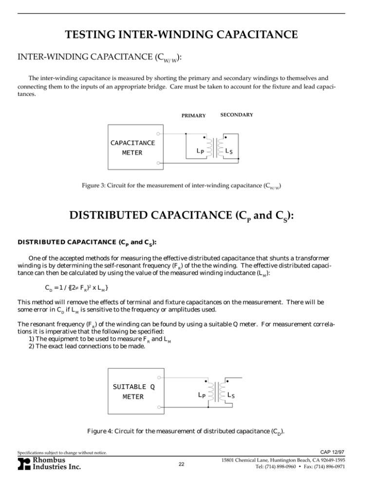
The inter-winding capacitance is measured by shorting the primary and secondary windings to themselves and
connecting them to the inputs of an appropriate bridge. Care must be taken to account for the fixture and lead capacitances.
PRIMARY
&$3$&,7$1&(
0(7(5
/3
SECONDARY
/6
Figure 3: Circuit for the measurement of inter-winding capacitance (CW/W)
DISTRIBUTED CAPACITANCE (CP and CS):
DISTRIBUTED CAPACITANCE (CP and CS):
One of the accepted methods for measuring the effective distributed capacitance that shunts a transformer
winding is by determining the self-resonant frequency (FR) of the the winding. The effective distributed capacitance can then be calculated by using the value of the measured winding inductance (LM):
CD = 1 / {(2π FR)2 x LM}
This method will remove the effects of terminal and fixture capacitances on the measurement. There will be
some error in CD if LM is sensitive to the frequency or amplitudes used.
The resonant frequency (FR) of the winding can be found by using a suitable Q meter. For measurement correlations it is imperative that the following be specified:
1) The equipment to be used to measure FR and LM
2) The exact lead connections to be made.
68,7$%/(4
0(7(5
/3
/6
Figure 4: Circuit for the measurement of distributed capacitance (CD).
CAP 12/97
Specifications subject to change without notice.
Rhombus
Industries Inc.
22
15801 Chemical Lane, Huntington Beach, CA 92649-1595
Tel: (714) 898-0960 • Fax: (714) 896-0971


