PowerPact® H- and J-Frame Circuit Breakers
Section 3—Accessories
Rotary Operating Handles
Directly-Mounted Rotary Operating Handles
Installation
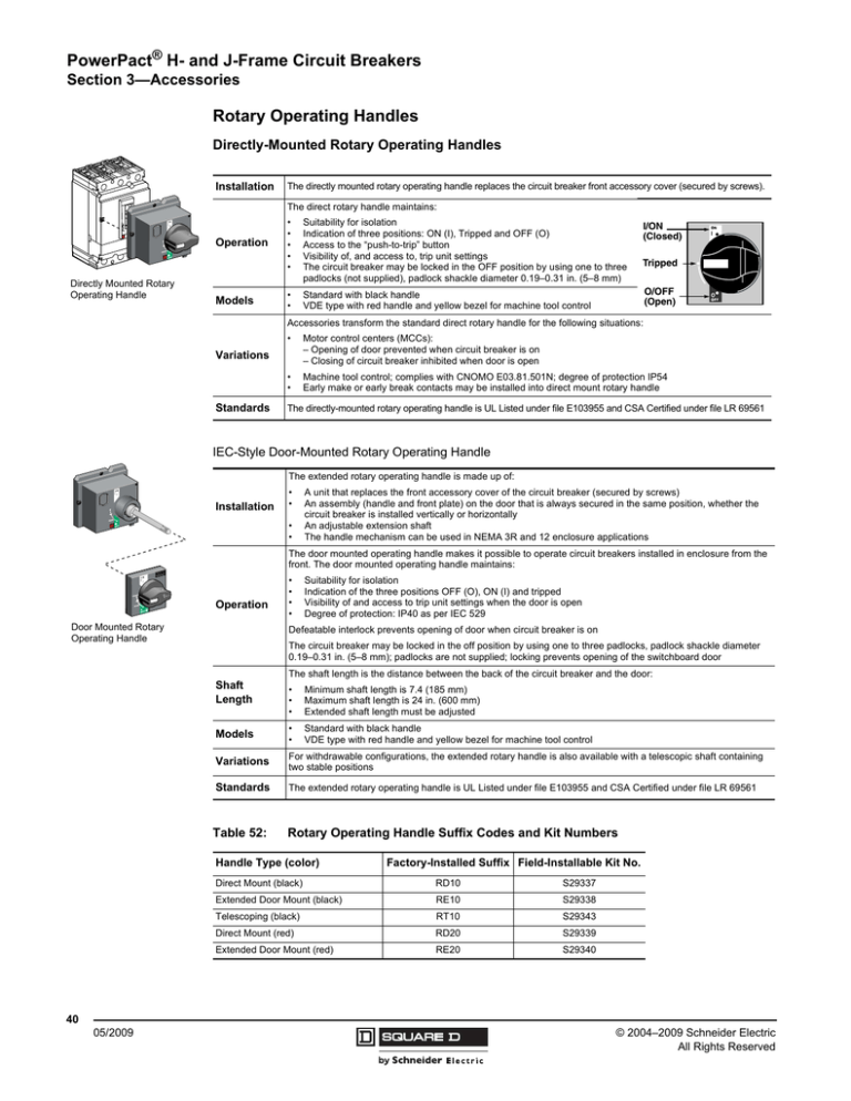
The directly mounted rotary operating handle replaces the circuit breaker front accessory cover (secured by screws).
The direct rotary handle maintains:
Operation
Directly Mounted Rotary
Operating Handle
Models
•
•
•
•
•
Suitability for isolation
Indication of three positions: ON (I), Tripped and OFF (O)
Access to the “push-to-trip” button
Visibility of, and access to, trip unit settings
The circuit breaker may be locked in the OFF position by using one to three
padlocks (not supplied), padlock shackle diameter 0.19–0.31 in. (5–8 mm)
•
•
Standard with black handle
VDE type with red handle and yellow bezel for machine tool control
I/ON
(Closed)
Tripped
O/OFF
(Open)
Accessories transform the standard direct rotary handle for the following situations:
•
Motor control centers (MCCs):
– Opening of door prevented when circuit breaker is on
– Closing of circuit breaker inhibited when door is open
•
•
Machine tool control; complies with CNOMO E03.81.501N; degree of protection IP54
Early make or early break contacts may be installed into direct mount rotary handle
Variations
Standards
The directly-mounted rotary operating handle is UL Listed under file E103955 and CSA Certified under file LR 69561
IEC-Style Door-Mounted Rotary Operating Handle
The extended rotary operating handle is made up of:
Installation
•
•
•
•
A unit that replaces the front accessory cover of the circuit breaker (secured by screws)
An assembly (handle and front plate) on the door that is always secured in the same position, whether the
circuit breaker is installed vertically or horizontally
An adjustable extension shaft
The handle mechanism can be used in NEMA 3R and 12 enclosure applications
The door mounted operating handle makes it possible to operate circuit breakers installed in enclosure from the
front. The door mounted operating handle maintains:
Operation
Door Mounted Rotary
Operating Handle
•
•
•
•
Suitability for isolation
Indication of the three positions OFF (O), ON (I) and tripped
Visibility of and access to trip unit settings when the door is open
Degree of protection: IP40 as per IEC 529
Defeatable interlock prevents opening of door when circuit breaker is on
The circuit breaker may be locked in the off position by using one to three padlocks, padlock shackle diameter
0.19–0.31 in. (5–8 mm); padlocks are not supplied; locking prevents opening of the switchboard door
The shaft length is the distance between the back of the circuit breaker and the door:
Shaft
Length
•
•
•
Minimum shaft length is 7.4 (185 mm)
Maximum shaft length is 24 in. (600 mm)
Extended shaft length must be adjusted
Models
•
•
Standard with black handle
VDE type with red handle and yellow bezel for machine tool control
Variations
For withdrawable configurations, the extended rotary handle is also available with a telescopic shaft containing
two stable positions
Standards
The extended rotary operating handle is UL Listed under file E103955 and CSA Certified under file LR 69561
Table 52:
Rotary Operating Handle Suffix Codes and Kit Numbers
Handle Type (color)
Factory-Installed Suffix Field-Installable Kit No.
Direct Mount (black)
RD10
S29337
Extended Door Mount (black)
RE10
S29338
Telescoping (black)
RT10
S29343
Direct Mount (red)
RD20
S29339
Extended Door Mount (red)
RE20
S29340
40
05/2009
© 2004–2009 Schneider Electric
All Rights Reserved
PowerPact® H- and J-Frame Circuit Breakers
Section 1—General Information
Catalog Numbering
J
L
L
3
6
250
T
Poles
Amperage
H H-Frame
J J-Frame
2 2P
3 3P
150 15–15- A
250 150–250 A
000 Switch
L
M
P
F
A
S
N
D
K
— ABC (3P)
Trip Unit
— Standard Fixed Trip Unit (Suitable for reverse connection) 6 CBA (3P)
1 AB (2P)
F06 60 A H-Frame Only (No trip unit)
2 AC (2P)
F15 150 A H-Frame Only (No trip unit)
3 BA (2P)
F25 250 A J-Frame Only (No trip unit)
4 BC (2P)
T
Complete Circuit Breaker (Frame + removable trip unit)
5 CA (2P)
S15 150 A Molded Case Switch (H-Frame automatic switch)
6 CB (2P)
S17 175 A Molded Case Switch (J-Frame automatic switch)
S25 250 A Molded Case Switch (J-Frame automatic switch)
C
100% Continuous Current Rating (See page 42 for minimum enclosure size)
M71 30 A H-Frame Motor Circuit Protector (MCP)
M72 50 A H-Frame Motor Circuit Protector (MCP)
M73 100 A H-Frame Motor Circuit Protector (MCP)
M74 150 A H-Frame Motor Circuit Protector (MCP)
M75 250 A J-Frame Motor Circuit Protector (MCP)
D81 500 Vdc 150–175 A J-Frame Molded Case Circuit Breaker
D82 500 Vdc 200–250 A J-Frame Molded Case Circuit Breaker
Voltage
Lugs Line/Load Side
Lugs Line Side
Lugs Load Side
Bus Bar
I-Line
Rear Connected
Plug-in
Drawout
Reverse I-Line
6 600 Vac
Interruption Rating (kA) (See Table 1)
Table 1:
––––
Accessory Suffix Code (See Table 2)
I-Line® Phasing
Frame
Terminations
–
Interrupting Rating
UL/CSA/NOM
1
IEC 647-2 Icu/Ics
240 Vac
480 Vac
600 Vac
250 Vdc
500 Vdc1
500/525 Vac
250 Vdc
500 Vdc
D
25 kA
18 kA
14 kA
20 kA
—
25/25 kA
18/18 kA
14/14 kA
20 kA
20 kA
G
65 kA
35 kA
18 kA
20 kA
20 kA
65/65 kA
35/35 kA
18/18 kA
20 kA
20 kA
J
100 kA
65 kA
25 kA
20 kA
—
100/100 kA
65/65 kA
25/25 kA
20 kA
20 kA
L
125 kA
100 kA
50 kA
20 kA
—
125/125 kA
100/100 kA
50/50 kA
20 kA
20 kA
220/240 Vac 380/440/415 Vac
Special DC J-frame circuit breakers only.
Table 2:
Accessory Suffix Codes (Building Sequence as Listed)
(1) Auxiliary Switch
(3) Shunt Trip
(4) Undervoltage
Release UVR
Voltage
(5) Motor Operator
Suffix
Voltage
H-Frame
J-Frame
ML
48/60 Vac
S29440
S31548
Suffix
Contacts
Kit Number
Suffix
Kit Number Suffix
Kit Number
AA
1A/1B Standard
S29450
SK
S29384
UK
S29404
24 Vac
AB
2A/2B Standard
S29450 (2)
SL
S29385
UL
S29405
48 Vac
MA
120 Vac
S29433
S31540
AE
1A/1B Gold
S29482
SA
S29386
UA
S29406
120 Vac
MD
277 Vac
S29434
S31541
AF
2A/2B Gold
S29482 (2)
SD
S29387
UD
S29407
208–277 Vac
MH
380/480 Vac
S29435
S31542
SH
S29388
UH
S29408
380–480 Vac
MO
24/30 Vdc
S29436
S31543
SJ
S29389
UJ
S29409
525–600 Vac
MP
48/60 Vdc
S29437
S31544
SN
S29382
UN
S29402
12 Vdc
MR
110/130 Vdc
S29438
S31545
MS
250 Vdc
S29439
S31546
(2) Alarm/Overcurrent Trip Switch
Suffix
Switch
Kit Number
BC
Alarm Switch (SD) S29450
SO
S29390
UO
S29410
24 Vdc
BH
Alarm Switch (SD)
S29452
Low-level
SU
S29391
UU
S29411
30 Vdc
(6) IEC Style Rotary Handle
BD
SDE Standard
S29450 +
S29451
SP
S29392
UP
S29412
48 Vdc
BJ
SDE Low-level
S29452 +
S29451
SV
S29383
UV
S29403
60 Vdc
BE
SD and SDE
Standard
S29450 (2) +
S29451
SR
S29393
UR
S29413
125 Vdc
BK
SD and SDE
Low-level
S29452 (2) +
S29451
SS
S29394
US
S29414
250 Vdc
Suffix
Handle Type (color)
Kit
Number
RD10
Direct Mount (black)
S29337
RE10
Extended Door Mount (black) S29338
RT10
Telescoping (black)
RD20
Direct Mount (red)
S29339
RE20
Extended Door Mount (red)
S29340
S29343
8
05/2009
© 2004–2009 Schneider Electric
All Rights Reserved


