ARTIFICIAL (LUMPED ELEMENT) TRANSMISSION LINE (Part of
advertisement
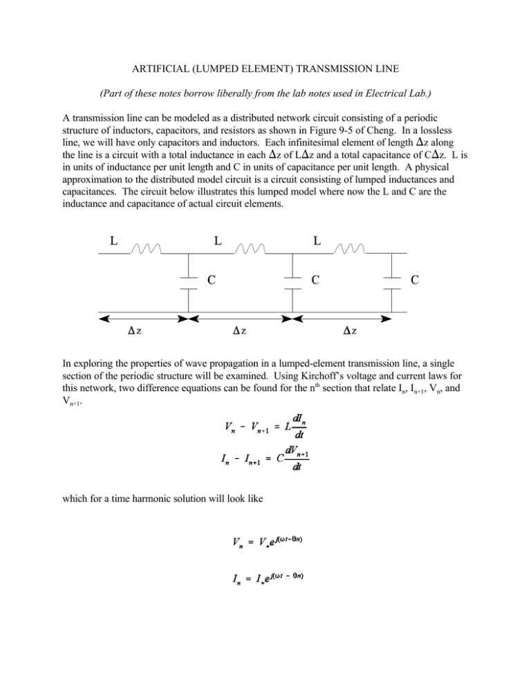
ARTIFICIAL (LUMPED ELEMENT) TRANSMISSION LINE (Part of these notes borrow liberally from the lab notes used in Electrical Lab.) A transmission line can be modeled as a distributed network circuit consisting of a periodic structure of inductors, capacitors, and resistors as shown in Figure 9-5 of Cheng. In a lossless line, we will have only capacitors and inductors. Each infinitesimal element of length )z along the line is a circuit with a total inductance in each )z of L)z and a total capacitance of C)z. L is in units of inductance per unit length and C in units of capacitance per unit length. A physical approximation to the distributed model circuit is a circuit consisting of lumped inductances and capacitances. The circuit below illustrates this lumped model where now the L and C are the inductance and capacitance of actual circuit elements. In exploring the properties of wave propagation in a lumped-element transmission line, a single section of the periodic structure will be examined. Using Kirchoff’s voltage and current laws for this network, two difference equations can be found for the nth section that relate In, In+1, Vn, and Vn+1. which for a time harmonic solution will look like where T is the radian frequency, t is the time, 2 is the phase shift per section of the lumped-line and n is the index of the nth section. The + subscript indicates a traveling-wave solution that propagates from the input end to the output end of the lumped line. The solutions to first two equations are of forms analogous to the second two equations except that $z replaces 2n. where $ is the propagation constant of the continuous transmission line and z is the spatial variable along the line. The correspondence between the lumped and continuous lines is Plugging the lumped solutions into the wave equations gives Multiplying the first expression by the second (for a nontrivial solution) which can be rewritten as This last equation is the dispersion equation for the lumped line. That is, it relates the phase shift per section to the frequency T. In order for real solutions for 2 to exist and thus, - B # 2# B, and is periodic in 2B. Hence solutions for 2 and T need only be examined within the confines of the interval of 2 between -B and B. This interval is known as the principle band of 2. With the last equation, T is limited by hence an upper bound exists for T. This upper bound, Tc, is called the cutoff frequency. There are no traveling wave solutions for frequencies above Tc. This lumped element transmission line becomes an approximation to a continuous transmission line when the wavelength, 8, of electromagnetic waves propagating in the lumped line are much longer than the length of each lumped element section. Under this condition, the phase shift 2 associated with each section must be small. With 2 small, the dispersion relation can be approximated as and With this information, we can find the impedance relationship between V and I. Using the expressions for the voltage and current at the nth sections and the first equation, we obtain since 2 is small for each section. The characteristic impedance Zo is found then from just as with the continuous line. Thus, we can see that the lumped line performs like a continuous line as long as 2 is small which occurs when the frequency is well below cutoff.
