instruction sheet for 501900-11xx front corner led heads
advertisement
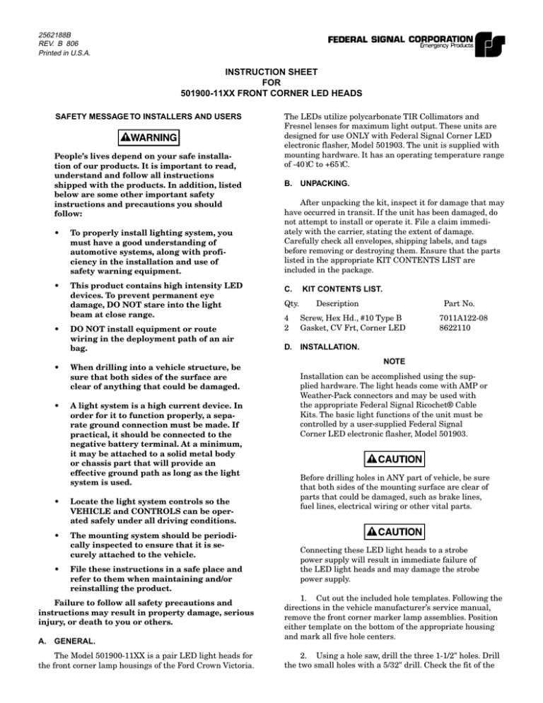
2562188B REV. B 806 Printed in U.S.A. INSTRUCTION SHEET FOR 501900-11XX FRONT CORNER LED HEADS SAFETY MESSAGE TO INSTALLERS AND USERS People’s lives depend on your safe installation of our products. It is important to read, understand and follow all instructions shipped with the products. In addition, listed below are some other important safety instructions and precautions you should follow: • To properly install lighting system, you must have a good understanding of automotive systems, along with proficiency in the installation and use of safety warning equipment. • This product contains high intensity LED devices. To prevent permanent eye damage, DO NOT stare into the light beam at close range. • • • DO NOT install equipment or route wiring in the deployment path of an air bag. When drilling into a vehicle structure, be sure that both sides of the surface are clear of anything that could be damaged. A light system is a high current device. In order for it to function properly, a separate ground connection must be made. If practical, it should be connected to the negative battery terminal. At a minimum, it may be attached to a solid metal body or chassis part that will provide an effective ground path as long as the light system is used. • Locate the light system controls so the VEHICLE and CONTROLS can be operated safely under all driving conditions. • The mounting system should be periodically inspected to ensure that it is securely attached to the vehicle. • File these instructions in a safe place and refer to them when maintaining and/or reinstalling the product. Failure to follow all safety precautions and instructions may result in property damage, serious injury, or death to you or others. A. GENERAL. The Model 501900-11XX is a pair LED light heads for the front corner lamp housings of the Ford Crown Victoria. The LEDs utilize polycarbonate TIR Collimators and Fresnel lenses for maximum light output. These units are designed for use ONLY with Federal Signal Corner LED electronic flasher, Model 501903. The unit is supplied with mounting hardware. It has an operating temperature range of -40°C to +65°C. B. UNPACKING. After unpacking the kit, inspect it for damage that may have occurred in transit. If the unit has been damaged, do not attempt to install or operate it. File a claim immediately with the carrier, stating the extent of damage. Carefully check all envelopes, shipping labels, and tags before removing or destroying them. Ensure that the parts listed in the appropriate KIT CONTENTS LIST are included in the package. C. Qty. KIT CONTENTS LIST. Description Part No. 4 2 Screw, Hex Hd., #10 Type B Gasket, CV Frt, Corner LED D. INSTALLATION. 7011A122-08 8622110 NOTE Installation can be accomplished using the supplied hardware. The light heads come with AMP or Weather-Pack connectors and may be used with the appropriate Federal Signal Ricochet® Cable Kits. The basic light functions of the unit must be controlled by a user-supplied Federal Signal Corner LED electronic flasher, Model 501903. Before drilling holes in ANY part of vehicle, be sure that both sides of the mounting surface are clear of parts that could be damaged, such as brake lines, fuel lines, electrical wiring or other vital parts. Connecting these LED light heads to a strobe power supply will result in immediate failure of the LED light heads and may damage the strobe power supply. 1. Cut out the included hole templates. Following the directions in the vehicle manufacturer’s service manual, remove the front corner marker lamp assemblies. Position either template on the bottom of the appropriate housing and mark all five hole centers. 2. Using a hole saw, drill the three 1-1/2" holes. Drill the two small holes with a 5/32" drill. Check the fit of the LED light head in the housing. Deburr all the holes. Then, thoroughly clean the housings to remove all chips. F. TESTING. This product contains high output LED devices. To prevent permanent eye damage, do not stare into the light beam at close range. The surfaces to which the adhesive gasket is applied must be clean and dry for proper adhesion. If necessary, use isopropyl alcohol (rubbing alcohol) and water to clean the mounting surface. After installation, check the entire system to be sure the lights are flashing properly and all light system functions are operating properly. 3. Peel the backing from the appropriate side of the gasket and apply the gasket to the LED light head. Peel the remaining backing and insert the LED light head into the housing. SAFETY MESSAGE TO OPERATORS People’s lives depend on your safe use of our products. Do not over-tighten the screws. Listed below are some important safety instructions and precautions you should follow: 4. Install the supplied screws using care not to cock the LED light head. • Although your warning system is operating properly, it may not be completely effective. People may not see or heed your warning signal. You must recognize this fact and continue driving cautiously. • Also, situations may occur which obstruct your warning signal when natural or manmade objects are between your vehicle and others, such as: raising your hood or trunk lid. If these situations occur, be especially careful. • At the start of your shift, you should ensure that the light is securely attached and operating properly. 5. Seal the perimeter of the LED light head with RTV (user-supplied) to maximize moisture protection. 6. E. Repeat steps 1 - 5 for the opposite side. ELECTRICAL. See figure 1 and refer to the instructions supplied with the Federal Signal Corner LED electronic flasher. AMP CONNECTOR 32 3 - NOT USED ON LED LIGHT HEAD TO HEAD BL Failure to follow these safety precautions may result in property damage, serious injury, or death to you, to passengers, or to others. 1 K RE D RETAIN AND REFER TO THIS MESSAGE AMP 3 POSITION CONNECTOR SUPPLIED ON LED LIGHHT HEAD. H. REPLACEMENT PARTS. CAUTION ENSURE THAT THE CORRECT WIRE COLOR SEQUENCE IS MAINTAINED AT ALL CONNECTIONS FROM THE LED LIGHT HEAD TO THE FLASHER. WEATHER-PACK CONNECTOR C B A C - NOT USED BL K RE PLUG (413300 ASSEMBLY) D Color Part No. LED assy., BLU LF CV, AMP LED assy., RED LF CV, AMP LED assy., WHT LF CV, AMP LED assy., BLU RF CV, AMP LED assy., RED RF CV, AMP LED assy., WHT RF CV, AMP LED assy., BLU LF CV, Weather-Pack LED assy., RED LF CV, Weather-Pack LED assy., WHT LF CV, Weather-Pack LED assy., BLU RF CV, Weather-Pack LED assy., RED RF CV, Weather-Pack LED assy., WHT RF CV, Weather-Pack 8622129-03 8622129-04 8622129-05 8622130-03 8622130-04 8622130-05 8622129-13 8622129-14 8622129-15 8622130-13 8622130-14 8622130-15 Manufactured by: Federal Signal Corporation Emergency Products Group 2645 Federal Signal Drive University Park, Illinois 60466 290A5389B Figure 1. Copyright 2005 Federal Signal Corporation -2- PASSENGER SIDE DRIVER SIDE 290A5388 Hole Templates
