Why hybrid vehicles?
advertisement
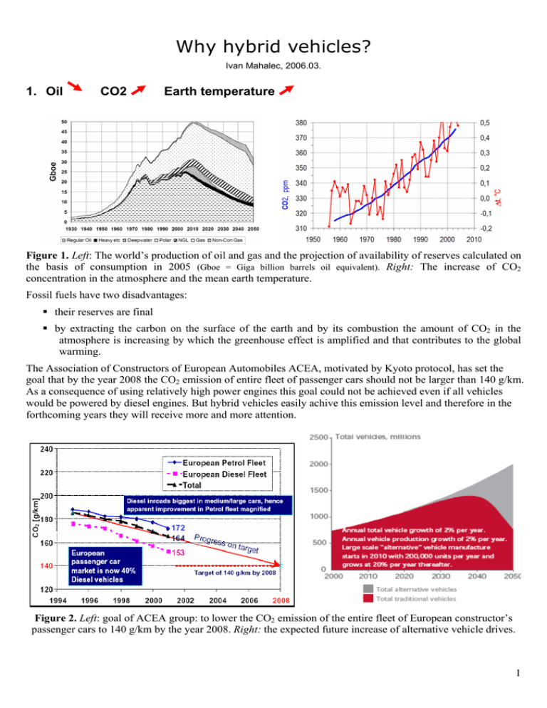
Why hybrid vehicles? Ivan Mahalec, 2006.03. 1. Oil CO2 Earth temperature Figure 1. Left: The world’s production of oil and gas and the projection of availability of reserves calculated on the basis of consumption in 2005 (Gboe = Giga billion barrels oil equivalent). Right: The increase of CO2 concentration in the atmosphere and the mean earth temperature. Fossil fuels have two disadvantages: their reserves are final by extracting the carbon on the surface of the earth and by its combustion the amount of CO2 in the atmosphere is increasing by which the greenhouse effect is amplified and that contributes to the global warming. The Association of Constructors of European Automobiles ACEA, motivated by Kyoto protocol, has set the goal that by the year 2008 the CO2 emission of entire fleet of passenger cars should not be larger than 140 g/km. As a consequence of using relatively high power engines this goal could not be achieved even if all vehicles would be powered by diesel engines. But hybrid vehicles easily achive this emission level and therefore in the forthcoming years they will receive more and more attention. Figure 2. Left: goal of ACEA group: to lower the CO2 emission of the entire fleet of European constructor’s passenger cars to 140 g/km by the year 2008. Right: the expected future increase of alternative vehicle drives. 1 2. Hybrid drive systems Hybrid drive systems can, on the basis of the link between mechanical and electrical part, be divided in three groups: series, paralel and series – paralel hybrid. On the other hand, on the basis of electrical drive autonomy, hybrids are divided into: mild hybrid and full hybrid. Series Bat Parallel Bat Wheels Inv Wheels Inv ICE Inv Seriesparallel Bat Gen ICE Gen EM EM Inv Mechanical energy path ICE PSD EM Electrical energy path Figure 3. Schematics of hybrid drives. Marks: Bat - battery; EM –electric motor; Gen –generator; Inv – inverter; ICE – internal combustion engine; PSD – power splitting device; published in [5.]. η = max HYBRID 120 Engine torque Me , (Nm) 100 240 246 80 250 60 vmax EG EG - for electric generator drive 260 40 V - for driving 300 20 Drive resistances v = konst., climb = 0 400 800 g/kWh 1000 2000 ∞ V 3000 4000 Engine speed, min-1 5000 6000 Figure 4. The comparison of internal combustion engine operation at conventional and hybrid vehicle in engine fuel consumption map. In the hybrid vehicle the internal combustion engine operates in the region of minimum specific fuel consumption, and the excess power, that is a result of difference between generated power and power needed for drive, is transferred to generator that charges the battery. In Prius the generator also supplies energy for electric motor that helps the IC engine 2 3. Fuel consumption and harmful emission Figure 5. Fuel consumption (l/100km) of three Prius hybrid generations and of similar conventional automobile. 14 l/100km 13 12 11 10 9 8 7 6 1975 290 g CO2/km (petrol) 250 g CO2/km (diesel) g CO2/km 210 170 Fuel consumption 1980 1985 1990 1995 2000 130 2005 Figure 6. The fuel consumption of the German vehicle fleet driven with new European drive cycle, according to the VDA data, and on the basis of this consumption the calculated emission of CO2. Figure 7. The efficiency of the Prius and its rivals based on Well-to-Wheel analysis. Figure 8. The harmful emission of the Prius. 3 4. Toyota Prius – the world’s no 1 Prius THS II Battery Power regulator Generator IC Engine Power splitting device High voltage part Inverter Electric motor Wheels Transmission Mechanical energy Electrical energy Figure 9. The schematics of drive system of hybrid vehicle Toyota Prius THS II. Characteristics: IC engine: 1.5 dm3, process 4-cycle Otto/Atkinson, reduced engine friction, PICE,max = 57 kW at 500 min-1, 115 NM at 4200 min-1, ge,min = 225 g/kWh (ηe,max = 37 %); electric motor: PEM,max = 50 kW; maximum total vehicle power 82 kW above 85 km/h (Pmax = PICE,max + 50 % (PEM,max)); 1300 kg; 0-100 km/h for 10,9 s; 170 km/h; 104 g CO2/km. 4 Figure 10. The Schematics of a drive system and of a power transmission system. 5 Figure 11. Toyota Prius: action schemes. Slika 12. Down - left: when braking Prius’s electric motor becomes generator. Figure 13. The characteristics of the IC engine (left) and of the electric motor (right). 6 Figure 14. Common action of IC engine and electric motor. Figure 15. Left: common action of IC engine and electric motor. Right: comparison of acceleration of Prius and of classic vehicle with petrol engine of 2.4 dm3. Figure 16. Comparison of acceleration of Prius and of classic vehicle with an equally strong diesel engine. 7 Figure 17. The electric drive system and the power transmission system. Figure 18. Ni-MH battery: 28 serially connected packages with 7,2 V = 202 V; 6,5 Ah; 30 kg; durability 300.000 km. 8
