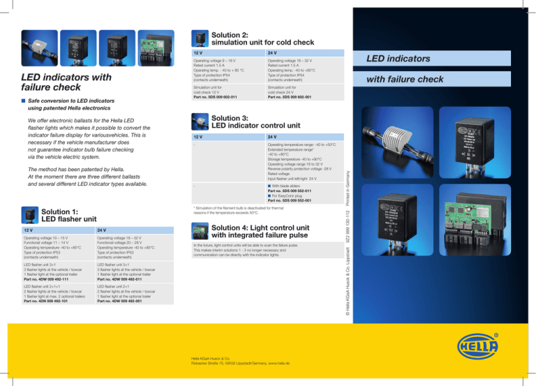
LED indicators with failure check
advertisement

Solution 2: simulation unit for cold check The method has been patented by Hella. At the moment there are three different ballasts and several different LED indicator types available. Simulation unit for cold check 12 V Part no. 5DS 009 602-011 Simulation unit for cold check 24 V Part no. 5DS 009 602-001 12 V 24 V Operating voltage 10 – 15 V Functional voltage 11 – 14 V Operating temperature -40 to +85°C Type of protection IP53 (contacts underneath) Operating voltage 18 – 32 V Functional voltage 20 – 28 V Operating temperature -40 to +85°C Type of protection IP53 (contacts underneath) LED flasher unit 3+1 3 flasher lights at the vehicle / towcar 1 flasher light at the optional trailer Part no. 4DW 009 492-111 LED flasher unit 3+1 3 flasher lights at the vehicle / towcar 1 flasher light at the optional trailer Part no. 4DW 009 492-011 LED flasher unit 2+1+1 2 flasher lights at the vehicle / towcar 1 flasher light at max. 2 optional trailers Part no. 4DN 009 492-101 LED flasher unit 2+1 2 flasher lights at the vehicle / towcar 1 flasher light at the optional trailer Part no. 4DW 009 492-001 with failure check Solution 3: LED indicator control unit 12 V 24 V - Operating temperature range: -40 to +50°C Extended temperature range* -40 to +80°C Storage temperature -40 to +90°C Operating voltage range 18 to 32 V Reverse polarity protection voltage -28 V Rated voltage input flasher unit left/right 24 V - ■■ With blade sliders Part no. 5DS 009 552-011 ■■ For EasyConn plug Part no. 5DS 009 552-001 * Simulation of the filament bulb is deactivated for thermal reasons if the temperature exceeds 50°C. Solution 1: LED flasher unit LED indicators Solution 4: Light control unit with integrated failure pulse In the future, light control units will be able to scan the failure pulse. This makes interim solutions 1 - 3 no longer necessary and communication can be directly with the indicator lights. Hella KGaA Hueck & Co. Rixbecker Straße 75, 59552 Lippstadt/Germany, www.hella.de Printed in Germany We offer electronic ballasts for the Hella LED flasher lights which makes it possible to convert the indicator failure display for variousvehicles. This is necessary if the vehicle manufacturer does not guarantee indicator bulb failure checking via the vehicle electric system. Operating voltage 18 – 32 V Rated current 1.5 A Operating temp. -40 to +85°C Type of protection IP54 (contacts underneath) 9Z2 999 130-112 ■■ Safe conversion to LED indicators using patented Hella electronics 24 V Operating voltage 9 – 16 V Rated current 1.5 A Operating temp. - 40 to + 85 °C Type of protection IP54 (contacts underneath) © Hella KGaA Hueck & Co. Lippstadt LED indicators with failure check 12 V Would you like to convert? We have the solution! Which is the right solution depends on the vehicle electronic. Product examples 2BA 959 070-631 Vehicle conversion Is there a flasher relay built in the vehicle? yes no Switch on vehicle ignition, and remove a bulb from the indicator without pressing the indicator switch. Failure of the flasher is indicated yes no Press indicator switch Failure of the flasher unit is indicated no Vehicle not ECE-conform Trailer conversion Solution 1: replacement of existing flasher unit by LED flasher unit from Hella with ISO pin basis One flasher unit per vehicle necessary. Every possible combination of bulbs and Hella LED indicators is allowed: from complete equipment with bulbs through mixed versions to complete equipment with LED lights. Bulbs or Hella LED indicators are also permitted on trailers. Solution 2: through simulation unit for cold check One simulation unit per LED light necessary. yes 2BA 959 050-401 Solution 3: through LED indicator control unit Two LED combination rearlights per vehicle can be monitored using one simulation unit. (Just on simulation device per vehicle can be used.) Solution 3: through LED indicator control unit 2BA 959 822-601 2BA 344.200-... failure pulse Start 2SD 344 100-... 2BA 343 390-... 2BA 008 982-... 2SD 343 910-...


